Advanced Outline Layer
m (use #C0C0C0 instead of #sliver as param list head bg color and <br /> instead of blank row at the end of the param list) |
(copyedit) |
||
| Line 3: | Line 3: | ||
{{Category|Layers}} | {{Category|Layers}} | ||
<!-- Page info end --> | <!-- Page info end --> | ||
| − | Under construction! TODO: add | + | Under construction! TODO: add hyperlinks for known words. Add some visual examples. |
{{l|Image:Layer_geometry_advanced_outline_icon.png|64px}} | {{l|Image:Layer_geometry_advanced_outline_icon.png|64px}} | ||
== About Advanced Outline Layers== | == About Advanced Outline Layers== | ||
| − | In the regular {{L|Outline Layer}} width ducks, defining outline width at particular place, are connected to the vertices, defining the outline shape. That means that user | + | In the regular {{L|Outline Layer}} width ducks, defining outline width at particular place, are connected to the vertices, defining the outline shape. That means that user needs to insert new a vertex on the bline every time he wants to change outline width in some place. This behaviour can cause problems when the shape of the outline is very simple but the width varies a lot. Practice shows that most of the time user needs to specify the width independently from the placement of [[BLine]] vertices. That functionality is available in Advanced Outline layer, which handles its width in a different way - the width ducks are freely moved around the bline and define its width at any point. |
| − | Additionally Advanced Outline introduces some new features to the regular outline. They are listed with examples below: | + | Additionally, Advanced Outline introduces some new features to the regular outline. They are listed with examples below: |
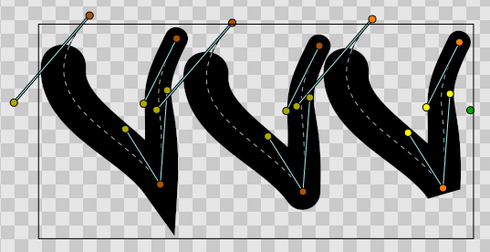
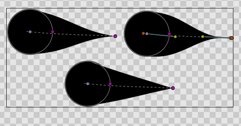
<gallery caption="New features" widths="490px" heights="300px" perrow="2"> | <gallery caption="New features" widths="490px" heights="300px" perrow="2"> | ||
File:Variable-width-without-blinepoints.png | No need to place vertex to change the width | File:Variable-width-without-blinepoints.png | No need to place vertex to change the width | ||
| Line 132: | Line 132: | ||
==Specific parameters for Advanced Outline Layer== | ==Specific parameters for Advanced Outline Layer== | ||
| − | Notice that many of the parameters are the same | + | Notice that many of the parameters are the same as the regular {{l|Outline Layer|Outline}}, so you can find the explanation of its usage by reading its wiki page. The new parameters are: |
* Tip Type at start | * Tip Type at start | ||
* Tip Type at end | * Tip Type at end | ||
| Line 140: | Line 140: | ||
=== Width Point List === | === Width Point List === | ||
| − | Each | + | Each Advanced Outline has a list of parameters that represent the information for each width item. They are called Width Points and consist of four sub-parameters: |
| − | * Position (Real number): | + | * Position (Real number): represents the position of the width point along the bline. Although it is allowed to be any real number, its meaning is only from 0.0 to 1.0. 0.0 corresponds to the start of the bline (first blinepoint on the bline list) and 1.0 to the last blinepoint. For looped blines 0.0 and 1.0 are equal. The position is represented by the light purple duck that always lies on the bline. |
| − | * Width (Real number): It is the width multiplicator of the global Width parameter of the Advanced Outline Layer on the position given by the Position parameter. The final width is calculated multiplying the global Advanced Outline's Width (W) by the Width of the | + | * Width (Real number): It is the width multiplicator of the global Width parameter of the Advanced Outline Layer on the position given by the Position parameter. The final width is calculated multiplying the global Advanced Outline's Width (W) by the Width of the widthpoint (w) and adding the Expand parameter (E). Calculated width = W*w+E |
* Tip Side Before/After: Those two sub-parameters controls how the width is interpolated before and after the current widthpoint. The sub-parameter can have four values: | * Tip Side Before/After: Those two sub-parameters controls how the width is interpolated before and after the current widthpoint. The sub-parameter can have four values: | ||
| − | ** Interpolate: Between the previous/ | + | ** Interpolate: Between the previous/following width point, the width is calculated by interpolation based on smoothness value. |
| − | ** Rounded: There is a rounded tip that points to the width point before or after. If the previous/ | + | ** Rounded: There is a rounded tip that points to the width point before or after. If the previous/following width point is 'Interpolate' on its posterior/previous side it considers that the width of the widthpoint in question is zero just before/after it. If the previous/posterior width point is other than 'Interpolate' then the segment between those two width points is empty. See examples to understand it fully. |
** Squared: Same as Rounded but using square tip. | ** Squared: Same as Rounded but using square tip. | ||
** Peak: Same as Rounded but using peak tip. | ** Peak: Same as Rounded but using peak tip. | ||
** Flat: Same as Rounded but using flat tip. | ** Flat: Same as Rounded but using flat tip. | ||
| − | The Width Point list has one internal | + | The Width Point list has one internal non-animatable parameter called ''loop''. You can reach it by right clicking the Width Point List parameter. If the Width Point list is unlooped, then any width point that has a Position outisde the range of [0,1] is clamped to (brought within) that range. For example: a Position = 1.35 is clamped to 1.0 then the Width Point List is unlooped. Otherwise, if the Width Point List is looped and a width point has a Position of 1.3, its modulus based on the range [0,1] is used, so it is turned to a position of 0.3. |
=== Smoothness === | === Smoothness === | ||
| − | The | + | The Smoothness controls how the width is calculated betwen widthpoints. The width at a position p is a function of the surrounding width points. When smoothness is zero interpolation is lineal, when smoothness is 1.0 interpolation is given by a 5th degree smooth spline. |
=== Cusp types === | === Cusp types === | ||
| Line 165: | Line 165: | ||
* Bevel | * Bevel | ||
| − | The type of cusp is controlled for the entire layer so currently it is not possible to control the type of corner individually. Maybe in future versions it | + | The type of cusp is controlled for the entire layer so currently it is not possible to control the type of corner individually. Maybe in future versions it will be possible. |
=== Tip type at start / end === | === Tip type at start / end === | ||
| − | As | + | As with width points, the end and start of the unlooped Advanced Outlines has a type of tip defined. The user can choose between the same types of tips as for a width point. When the first/last width point has its before/after interpolation type set to Interpolate the start/end of the outline is rendered using the Tip type at start/end parameter. |
| − | Those parameters | + | Those parameters don't have any effect if the bline is looped or the first/last width point has its before/after interpolation type set to anything but Interpolate. In that case, the segment between the start/end width point and the start/end of the bline is not rendered. |
| − | The types of tips are the same | + | The types of tips are the same as the width point tip types except that it doesn't offer the Interpolate type because it would not make sense: |
* Rounded | * Rounded | ||
* Squared | * Squared | ||
| Line 189: | Line 189: | ||
=== Change the width of the Width Points === | === Change the width of the Width Points === | ||
| − | Initially the width ducks are hidden. You | + | Initially the width ducks are hidden. You can make them visible by pressing Alt+5 or cliking on the width toggle button. It is possible to change the width using the Width Tool using the same procedure as for regular outlines. If you want more control over the width you can modify the width ducks with the Transform tool (Alt+A). More fine tunning is possible by expanding the width point sub-parameter and entering a specific value for the Width sub-parameter. In that case negative values are allowed to produce nice effects. |
| − | + | ||
=== Change the position of the Width Points === | === Change the position of the Width Points === | ||
| − | |||
| − | The position ducks of the width points can be modified using the Transform Tool (ALT-A) and | + | When you make the width ducks of the width points visible/invisible, the position ducks also become visible/invisible. (NOTE: this may change in the future). This way, the user has a single way to hide/show the position and width ducks. |
| + | |||
| + | The position ducks of the width points can be modified using the Transform Tool (ALT-A) and clicking and dragging the position duck. You will notice that ducks are tied to the bline so once clicked and dragged they can be placed at any way on the bline. Notice that if you have a width point position duck at position 0.2 and you click and drag at position 0.9 it may happen that you obtain a value of -0.1 because you dragged it in one step and the Width Point List may be looped. If you want to avoid those problems do the movement in small steps to indicate the correct path to follow when calculating the new position. | ||
=== Adding or removing width points === | === Adding or removing width points === | ||
To add a new width point you have to right click on the width point position duck purple duck to get the context menu. Then select "Add Item (smart)" here to create more width points entries. The width points are created this way: | To add a new width point you have to right click on the width point position duck purple duck to get the context menu. Then select "Add Item (smart)" here to create more width points entries. The width points are created this way: | ||
| − | In general case, the new widthpoint is created between the | + | In the general case, the new widthpoint is created between the width point you click on and the "previous" width point. Depending on the loop status of the bline, the "previous" width point can be the start of the bline (unlooped) or the last widthpoint (looped). The worst case is when there is only one width point on the Width Point List. If you add one new item it will lie over the existing one. |
| − | The | + | The newly added width point will have the interpolated width at the position where it is created. |
| − | {{Note|Warning|Be warned that if you remove all the width points you will use the width of the layer as the only one width but you will enter in | + | {{Note|Warning|Be warned that if you remove all the width points you will use the width of the layer as the only one width but you will enter in an unrecoverable status because it will be not possible to add a new width point. This is something that has to be fixed.}} |
=== Specific actions for Width Points === | === Specific actions for Width Points === | ||
| − | Some needed actions | + | Some needed actions have been added to width points as well as functionality for existing actions for items of the List type parameters. You can reach the list of available actions by right clicking on the width point position or directly on the width point item of the Width Point List. Here are some descriptions of the available actions: |
| − | * Convert: Width Points are composite Value Nodes so its natural format | + | * Convert: Width Points are composite Value Nodes so its natural format is Composite (you can access its componets). But you can convert it to other formats. See Convert for details. &&TODO: Update Convert wiki page&& |
| − | * Disconnect: This will disconnect the width point item | + | * Disconnect: This will disconnect the width point item from the Composite type Value Node. That means that there won't be any duck to show and that any of its values can be modified. Maybe it is useful for some types of workflows. To restore its Composite status, choose Convert->Composite. |
| − | * Insert/ Remove Item Smart: This will add or remove a width point. If in animation mode it will also set the current width point as OFF | + | * Insert/ Remove Item Smart: This will add or remove a width point. If Remove is used in animation mode, it will also set the current width point as OFF instead of effectively removing it from the Width Point List. Opposite for the Insert Item Smart. |
| − | * Mark Active Point as ON/OFF: You can | + | * Mark Active Point as ON/OFF: You can set width points off to make it not count for width control while the width point is off. When the width point is half on to off or viceversa, the used width point should be the interpolation between the on and off status. But it doesn't work properly at the moment. On / Off values are not interpolated but fully on or fully off. This has to be corrected. |
* Export: See Export. | * Export: See Export. | ||
| − | * Loop: When set as looped, as mentioned before, it allows the width point positions loop around the range[0 | + | * Loop: When set as looped, as mentioned before, it allows the width point positions loop around the range [0,1]. |
* Rotate Order: Doesn't do anything. | * Rotate Order: Doesn't do anything. | ||
| − | * Set Side Before/After to: Interpolate, Rounded, Squared, Peak, Flat. Those are shorcuts to do the same | + | * Set Side Before/After to: Interpolate, Rounded, Squared, Peak, Flat. Those are shorcuts to do the same as going directly to the sub-parameter and choosing the appropiate Tip Type. Maybe it should be renamed to "Set Tip Before/After". |
| − | * Set Width to default/zero: those actions have been | + | * Set Width to default/zero: those actions have been added for two reasons. It is very common to want to set the width of a width point to zero. Despite the possibility of use the User Preference of Restrict Radius to First Quadrant, this way it is accesed quickly from the same usual menu. Also when a width point position duck and a width point width duck are on top of each other (width = 0) it is hard to modify the width or the position without trouble. To solve this the position duck has preference over the width duck in case of coincidence. So access the width duck it is needed to have a quick action to set it to its default value (1.0). |
Revision as of 16:40, 20 August 2011
Under construction! TODO: add hyperlinks for known words. Add some visual examples.
Contents
About Advanced Outline Layers
In the regular Outline Layer width ducks, defining outline width at particular place, are connected to the vertices, defining the outline shape. That means that user needs to insert new a vertex on the bline every time he wants to change outline width in some place. This behaviour can cause problems when the shape of the outline is very simple but the width varies a lot. Practice shows that most of the time user needs to specify the width independently from the placement of BLine vertices. That functionality is available in Advanced Outline layer, which handles its width in a different way - the width ducks are freely moved around the bline and define its width at any point.
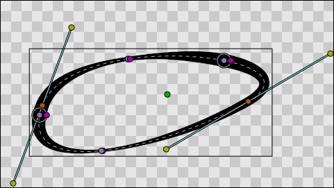
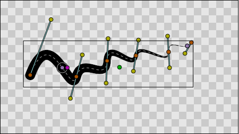
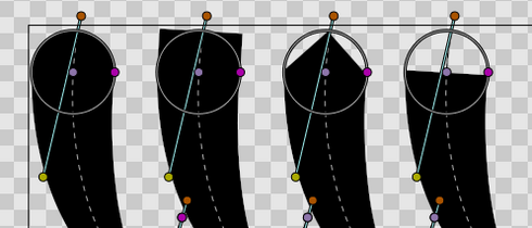
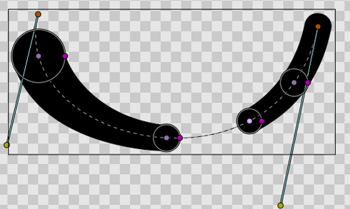
Additionally, Advanced Outline introduces some new features to the regular outline. They are listed with examples below:
- New features
Parameters of Advanced Outline Layers
The parameters of the Advanced Outline Layers are:
| Name | Value | Type |
| 0.000000 | real | |
| 1.000000 | real | |
| Composite | integer | |
|
|
color | |
| 0.000000u,0.000000u | vector | |
|
|
bool | |
|
|
bool | |
| 0.000000pt | real | |
| Fast Gaussian Blur | integer | |
| Non Zero | integer | |
| List | list (BLine) | |
| 2.000000pt | real | |
| 0.000000pt | real | |
| Rounded Stop | integer | |
| Rounded Stop | integer | |
| Sharp | integer | |
| 0.500000 | real | |
| List | list(WPList) |
Specific parameters for Advanced Outline Layer
Notice that many of the parameters are the same as the regular Outline, so you can find the explanation of its usage by reading its wiki page. The new parameters are:
- Tip Type at start
- Tip Type at end
- Cusps type
- Smoothness
- Width Point List
Width Point List
Each Advanced Outline has a list of parameters that represent the information for each width item. They are called Width Points and consist of four sub-parameters:
- Position (Real number): represents the position of the width point along the bline. Although it is allowed to be any real number, its meaning is only from 0.0 to 1.0. 0.0 corresponds to the start of the bline (first blinepoint on the bline list) and 1.0 to the last blinepoint. For looped blines 0.0 and 1.0 are equal. The position is represented by the light purple duck that always lies on the bline.
- Width (Real number): It is the width multiplicator of the global Width parameter of the Advanced Outline Layer on the position given by the Position parameter. The final width is calculated multiplying the global Advanced Outline's Width (W) by the Width of the widthpoint (w) and adding the Expand parameter (E). Calculated width = W*w+E
- Tip Side Before/After: Those two sub-parameters controls how the width is interpolated before and after the current widthpoint. The sub-parameter can have four values:
- Interpolate: Between the previous/following width point, the width is calculated by interpolation based on smoothness value.
- Rounded: There is a rounded tip that points to the width point before or after. If the previous/following width point is 'Interpolate' on its posterior/previous side it considers that the width of the widthpoint in question is zero just before/after it. If the previous/posterior width point is other than 'Interpolate' then the segment between those two width points is empty. See examples to understand it fully.
- Squared: Same as Rounded but using square tip.
- Peak: Same as Rounded but using peak tip.
- Flat: Same as Rounded but using flat tip.
The Width Point list has one internal non-animatable parameter called loop. You can reach it by right clicking the Width Point List parameter. If the Width Point list is unlooped, then any width point that has a Position outisde the range of [0,1] is clamped to (brought within) that range. For example: a Position = 1.35 is clamped to 1.0 then the Width Point List is unlooped. Otherwise, if the Width Point List is looped and a width point has a Position of 1.3, its modulus based on the range [0,1] is used, so it is turned to a position of 0.3.
Smoothness
The Smoothness controls how the width is calculated betwen widthpoints. The width at a position p is a function of the surrounding width points. When smoothness is zero interpolation is lineal, when smoothness is 1.0 interpolation is given by a 5th degree smooth spline.
Cusp types
There are three types of cusps in the Advanced Outline:
- Sharp
- Rounded
- Bevel
The type of cusp is controlled for the entire layer so currently it is not possible to control the type of corner individually. Maybe in future versions it will be possible.
Tip type at start / end
As with width points, the end and start of the unlooped Advanced Outlines has a type of tip defined. The user can choose between the same types of tips as for a width point. When the first/last width point has its before/after interpolation type set to Interpolate the start/end of the outline is rendered using the Tip type at start/end parameter.
Those parameters don't have any effect if the bline is looped or the first/last width point has its before/after interpolation type set to anything but Interpolate. In that case, the segment between the start/end width point and the start/end of the bline is not rendered.
The types of tips are the same as the width point tip types except that it doesn't offer the Interpolate type because it would not make sense:
- Rounded
- Squared
- Peak
- Flat
Working with the Avdanced Outline
Creation of the Advanced Outline
You can create Advanced Outlines in the same way that you make normal ones with the BLine Tool (Alt+B), but make sure the Advanced Outline box is ticked in the bline toolbox. Alternatively you can create a default Advanced Outline by clicking in the menu Insert-> Layer->Geometry->Advanced Outline.
Currently it is not possible to create Advanced Outlined with the Draw Tool. It has been postponed to a future release.
Change the width of the Width Points
Initially the width ducks are hidden. You can make them visible by pressing Alt+5 or cliking on the width toggle button. It is possible to change the width using the Width Tool using the same procedure as for regular outlines. If you want more control over the width you can modify the width ducks with the Transform tool (Alt+A). More fine tunning is possible by expanding the width point sub-parameter and entering a specific value for the Width sub-parameter. In that case negative values are allowed to produce nice effects.
Change the position of the Width Points
When you make the width ducks of the width points visible/invisible, the position ducks also become visible/invisible. (NOTE: this may change in the future). This way, the user has a single way to hide/show the position and width ducks.
The position ducks of the width points can be modified using the Transform Tool (ALT-A) and clicking and dragging the position duck. You will notice that ducks are tied to the bline so once clicked and dragged they can be placed at any way on the bline. Notice that if you have a width point position duck at position 0.2 and you click and drag at position 0.9 it may happen that you obtain a value of -0.1 because you dragged it in one step and the Width Point List may be looped. If you want to avoid those problems do the movement in small steps to indicate the correct path to follow when calculating the new position.
Adding or removing width points
To add a new width point you have to right click on the width point position duck purple duck to get the context menu. Then select "Add Item (smart)" here to create more width points entries. The width points are created this way:
In the general case, the new widthpoint is created between the width point you click on and the "previous" width point. Depending on the loop status of the bline, the "previous" width point can be the start of the bline (unlooped) or the last widthpoint (looped). The worst case is when there is only one width point on the Width Point List. If you add one new item it will lie over the existing one.
The newly added width point will have the interpolated width at the position where it is created.
|
Warning Be warned that if you remove all the width points you will use the width of the layer as the only one width but you will enter in an unrecoverable status because it will be not possible to add a new width point. This is something that has to be fixed.
|
Specific actions for Width Points
Some needed actions have been added to width points as well as functionality for existing actions for items of the List type parameters. You can reach the list of available actions by right clicking on the width point position or directly on the width point item of the Width Point List. Here are some descriptions of the available actions:
- Convert: Width Points are composite Value Nodes so its natural format is Composite (you can access its componets). But you can convert it to other formats. See Convert for details. &&TODO: Update Convert wiki page&&
- Disconnect: This will disconnect the width point item from the Composite type Value Node. That means that there won't be any duck to show and that any of its values can be modified. Maybe it is useful for some types of workflows. To restore its Composite status, choose Convert->Composite.
- Insert/ Remove Item Smart: This will add or remove a width point. If Remove is used in animation mode, it will also set the current width point as OFF instead of effectively removing it from the Width Point List. Opposite for the Insert Item Smart.
- Mark Active Point as ON/OFF: You can set width points off to make it not count for width control while the width point is off. When the width point is half on to off or viceversa, the used width point should be the interpolation between the on and off status. But it doesn't work properly at the moment. On / Off values are not interpolated but fully on or fully off. This has to be corrected.
- Export: See Export.
- Loop: When set as looped, as mentioned before, it allows the width point positions loop around the range [0,1].
- Rotate Order: Doesn't do anything.
- Set Side Before/After to: Interpolate, Rounded, Squared, Peak, Flat. Those are shorcuts to do the same as going directly to the sub-parameter and choosing the appropiate Tip Type. Maybe it should be renamed to "Set Tip Before/After".
- Set Width to default/zero: those actions have been added for two reasons. It is very common to want to set the width of a width point to zero. Despite the possibility of use the User Preference of Restrict Radius to First Quadrant, this way it is accesed quickly from the same usual menu. Also when a width point position duck and a width point width duck are on top of each other (width = 0) it is hard to modify the width or the position without trouble. To solve this the position duck has preference over the width duck in case of coincidence. So access the width duck it is needed to have a quick action to set it to its default value (1.0).
