Calque de Contour
--- Page en cours de traduction --- Merci de patientez et/ou contribuez
Contents
A propos des Calques de Contour
Les Calques de Contour sont utilisés pour manipuler les bordures et contours des formes pleines. Elle produisent un effet dessin animé à une animation lorsqu'ils sont ajoutés en tant que contour de formes pleines. Également les Calques de Contour, utilisés seul, sont utiles pour définir les bordures de formes 3D. Utilisés avec des ombres (créé avec les dégradés ou l'adoucissement) vous obtenez la base d'un travail d'artiste.
Pour créer un Calque de Contour, utilisez l'BLine Tool/fr et cochez Créer un contour (BLine) dans le panneau d'options des outils. Une fois que vous avez définit la géométrie de votre contour et après avoir pressé le bouton Créer (ou sélectionné un autre outil ou état) vous avez créé le Calque de Contour avec la couleur de premier plan actuelle (Couleur de contour).
Paramètres des Calques de Contour
Les paramètres des Calques de Contour sont:
| Nom | Valeur | Type |
| 0.000000 | nombre réel | |
| 1.000000 | nombre réel | |
| Composite | nombre entier | |
|
|
couleur | |
| 0.000000u,0.000000u | vecteur | |
|
|
booléen | |
|
|
booléen | |
| 0.000000pt | nombre réel | |
| Fast Gaussian Blur | nombre entier | |
| Non Zero | nombre entier | |
| List | liste (BLine) | |
| 2.000000pt | nombre réel | |
| 0.000000pt | nombre réel | |
|
|
booléen | |
|
|
booléen | |
|
|
booléen | |
| 1.000000 | nombre réel | |
|
|
booléen |
Specific parameters for Outline Layers
The first 11 parameters of the Outline are common parameter that are shared for several types of Layers. Click on the links to see their definitions. Only the particular parameters for the Outline Layer are described here.
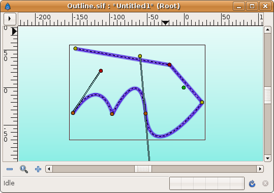
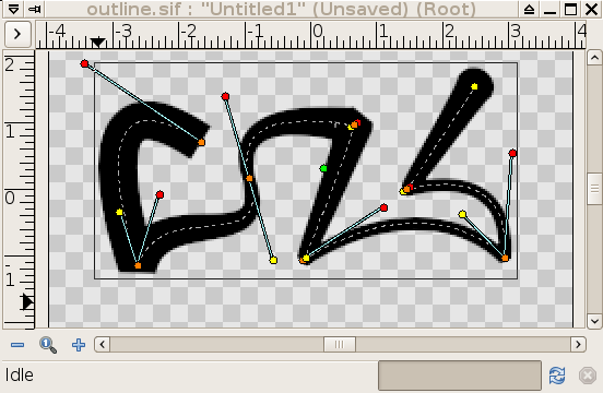
This is a sample screen shot of an Outline Layer in action:
Outline width
The Outline width parameter is a float value in pixels that represents the basic value of the width for all the points of the curve at the same time. It works together with the width parameter of the vertices' child values. So setting the Outline Width to 1.0px then the resulting value for the rendered width in that vertex comes from this formula: W = OLW * VW + 2E.
Where:
- W = resulting width of the outline at that vertex.
- OLW = overall parameter for the width of all the vertices (that is the Outline Width parameter).
- VW = specific vertex width value.
- E = value of the Expand parameter.
The width duck would show the radius value for that vertex (W/2).
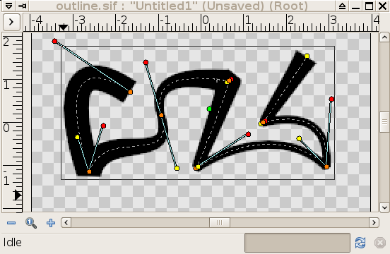
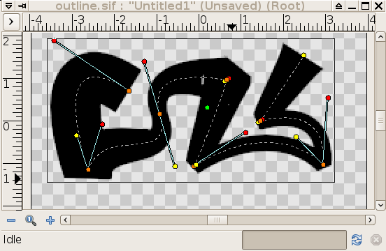
The width that ends up being used for each vertex is ((VertexWidth * OutLineWidth) + Expand*2):
|
|
| starting image | after doubling the value of 'outline width' |
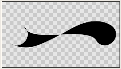
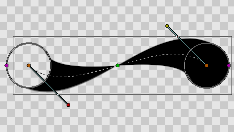
It's possible to specify negative values for the width values, which kind of turns the vertex inside out. Here's an example where the left vertex has a negative width and the right has a positive width. Note how the edges of the bline between the vertices cross each other in the middle:
|
|
Expand
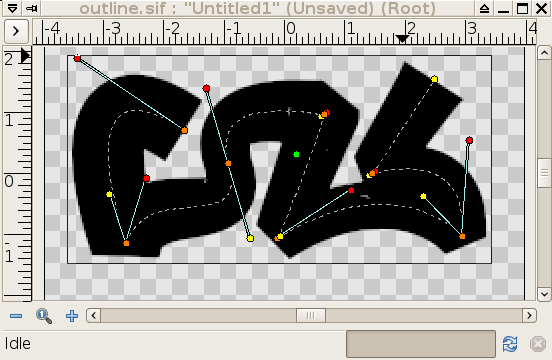
The Expand parameter is similar to the Outline Width parameter, but rather than being multiplied by each vertex's width, it is added to the radius of each vertex. In other words (2*Expand) is added to the diameter of each vertex.
The width that ends up being used for each vertex is ((VertexWidth * OutLineWidth) + Expand*2):

|
|
| zero 'expand' | non-zero 'expand' |
Sharp cups
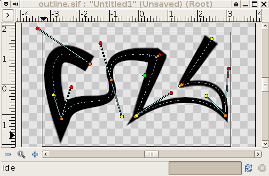
Enabling 'sharp cusps' makes the corners pointy when the tangents are split:

|
|
| no sharp cusps | sharp cusps |
Rounded Begin
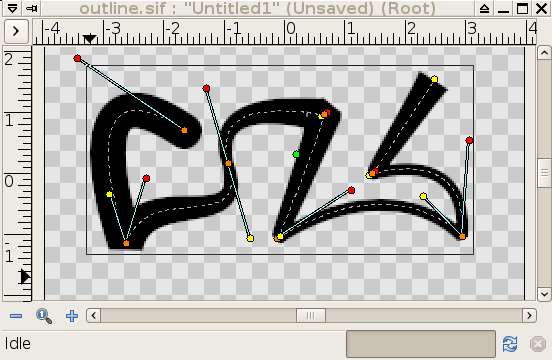
Enabling 'rounded begin' makes the start of the outline rounded:

|
|
| no rounded begin | rounded begin |
Rounded End
Enabling 'rounded end' makes the end of the outline rounded:

|
|
| no rounded end | rounded end |
Loopyness
This parameter currently does absolutely nothing at all!
Homogeneous
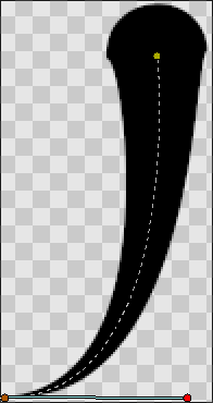
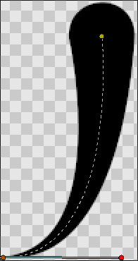
Enabling 'Homogeneous' changes the way that the width of the outline changes from one blinepoint to the next. Each point in the bline has its own width, and the bline has its own 'Outline Width' and 'Expand' parameters which are used to give the final width at each blinepoint. The 'Homogeneous' parameter controls how the width is interpolated between two neighbouring blinepoints:
- When 'Homogeneous' isn't checked, the width is interpolated linearly with the spline's 't' parameter.
- When 'Homogeneous' is checked, the width is interpolated linearly with the spline's length.
Turning off homogeneous often makes the fat end of a bline look lumpy. Maybe that's a bug:
|
|
| not homogeneous | homogeneous |
Misc
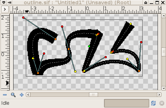
The 'antialias' checkbox isn't specific to the Outline layer, but it is particularly useful for the Outline layer. It makes the edges appear smoother:
|

|
| not antialiased | antialiased |

