Spline Tool
From Synfig Studio :: Documentation
Revision as of 08:40, 27 February 2013 by D.j.a.y (Talk | contribs) (Screenshots_Update / some syntax also)
Introduction
Splines are the most used object in any normal animation done with Synfig, and the Spline Tool allows you to create them.
Usage
The "Spline Tool" button puts you in a create Spline mode. To leave that mode just select another tool from the toolbox. It is easy to use this tool:
- Single click creates new vertices. "Tangent" value is set to (0,0) and the vertex becomes a sharp corner.
- Click and drag creates new vertices and allows the modification of the tangent value at that vertex. Extending the tangent smooths the corners.
- Each new vertex is attached to the previous by a "Bézier spline" defined by the vertices's position and it's tangents.
- The Spline is created sequentially; One vertex follows another.
- The end point of the previous Spline arc guides the next arc created until you close it. The next created Spline will be independent of the previously created Spline.
- You can tweak the newly created vertices by clicking on ducks and dragging them.
- You can also right click on a vertex duck or a tangent duck and it will provide a context menu:
- For tangent ducks: "Split tangents" will split the tangent so that you can independently modify the arch of an end point of a bézier curve. "Merge tangents" will merge the independent tangents so that you can align the arches of the end points of two connecting bézier curves.
- For vertex ducks: "Loop Spline" or "UnLoop Spline" (depending on if it is already looped or not) allows you to close or open the spline. "Delete vertex" allows you to delete the vertex.
- You can also right click in the middle of a bézier curve. "Insert vertex" allows insertion of a vertex (and set its tangents intelligently according to the neighboring vertices' values) where you clicked.
To finish the Spline:
- Select other tool.
- Or click on the gear button of the Tool Options Panel.
To clear out the working Spline, press the Esc button.
Options
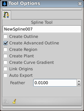
This tool has the following options:
- Spline Layer name. The name of the Spline that you will create is set by the text input box. In this case it is "Spline141". This input text will parse the end of the string if any integer number is found, increasing that number for the next time you create other Spline. If not number is found it adds a three digit number for the next Spline created.
- Advanced Outline check box. If checked it creates an Advanced Outline Layer.
- Outline check box. If checked it creates an Outline Layer.
- Fill check box. If checked it creates a Region Layer.
- Plant check box. If checked it creates a Plant Layer.
- Gradient check box. If checked it creates a Curved Gradient.
- Link Offsets check box. If enabled it links the Offset Parameter for the Plant, Region or Outline if two of them (or all them) are checked.
- Auto Export check box. If checked it automatically exports the Vertices parameter (that's a Spline type parameter)
- Feather numerical input field. There you set the feather parameter of the Region Layer or Outline Layer created.
Other sources of information
See this video tutorial to see it in action.
Read Creating Shapes which talks a little about the Spline tool.
Read Spline Speed which explains about variations in the Amount parameter of Splines.
