Curve Warp Layer
Contents
About Curve Warp Layer
Curve Warp Layers maps the context where it is applied from a straight line to a curved bezier shape. Each point on the source context can be defined by two perpendicular coordinates values based on the position and the length of the source straight line. Those coordinates are like the X and Y coordinates of a scaled and rotated 2D coordinate system.
Then each pair of coordinates is mapped onto the curve considering that the distance from the start point of the curve (the X coordinate) and the perpendicular distance to the straight line (the Y coordinate) are now the length of the spline from the first splinepoint and the perpendicular distance to the curve on that point.
Parameters of Curve Warp Layer
The parameters of the Curve Warp Layer are:
| Name | Value | Type | |
| 0.000000pt,0.000000pt | vector | ||
| 5.500000pt | real | ||
| -150.0000pt,-30.00000pt | vector | ||
| 150.00000pt,-18.00000pt | vector | ||
| List | Spline | ||
| |
bool |
Using a Curve Warp
Curve Warp layer is inside the Distortion sub menu of the New Layer menu. There is no tool to create this type of layer.
Let's show how to use a Curve Warp layer and what's the effect it produces by a direct example.
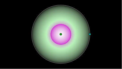
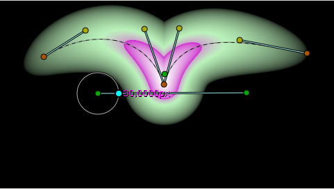
I first create one radial gradient at the center of the screen. I modified the default gradient to give me that result.
Then we create a Warp Layer over that radial gradient layer.
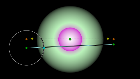
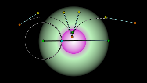
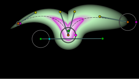
When you first create the Warp Layer you obtain a almost straight horizontal line defined by two points (below) and a slightly moved spline curve near it (above). I've disabled the curve warp layer on the screen shot to allow to see clearly the handles of the curve warp layer. The straight line defines the source coordinate system where for the context. The Spline defines the curve that is going to be used to map the context along the curve. Let's edit the curve warp components by placing the straight line along the green area of the gradient and inserting another splinepoint on the curve and tweaking the position of the tangents and vertexes.
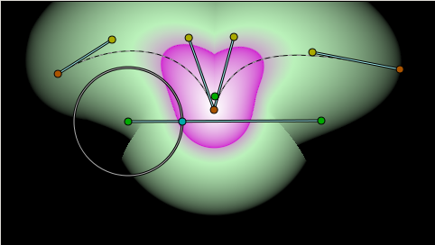
Let's enable the curve warp layer to see the effect.
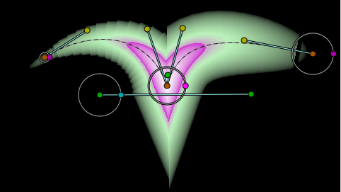
As you can now understand, the context is read based on the straight line position and mapped along the spline from the first to the last vertex. Due to the curvature of the spline, there are points from the source that are mapped on the same place, and so some kind of render artifact is produced. It can be view like a feature if some kind of special effect is wanted to be achieved.
There is one radial handle over the first point of the straight line. It has two missions:
- First, it defines the perpendicular width of the mapped result.
- Second, it is placed on the start point of the straight line.
If we decrease the width the effect is that the whole warp is stretched in the perpendicular direction of the line and the curve.
It defines the global width but it is possible to use the local width of the splinepoints to modify the width along the spline. Enable the visibiity of the width handles and modify them.
Fast Option
The above screen shots were taken using the Fast option disabled. When enabled, calculations are made in a rough mode what produces more artifacts but it renders faster.
Other examples
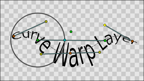
Curve warp layer are ideal for curved texts...
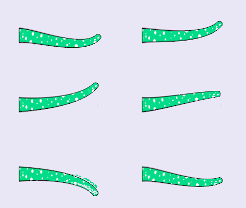
Tails, tentacles...
Source file: File:Tail.sifz
| Language: |
English |
