Sewing Splines
Somes of the screenshots needs to be updated with 0.64.0
This is a small tutorial that describes how to join any layers based on the Spline object by their edges. Such layers include the Region Layers, Outline Layers, Plant Layer and Curve Gradient Layer.
Contents
Problem Definition
It is not always possible to link the edges of the Splines, because they may have been constructed in opposite directions (clockwise and counter clockwise), causing the tangents not to be appropriate for linking to each other.
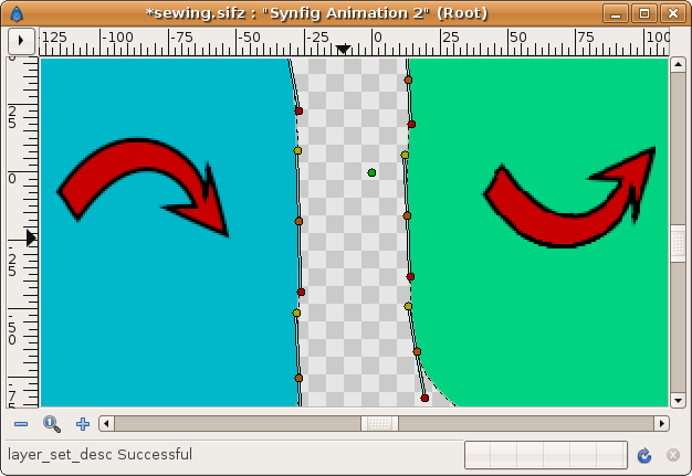
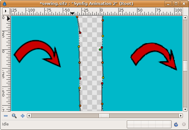
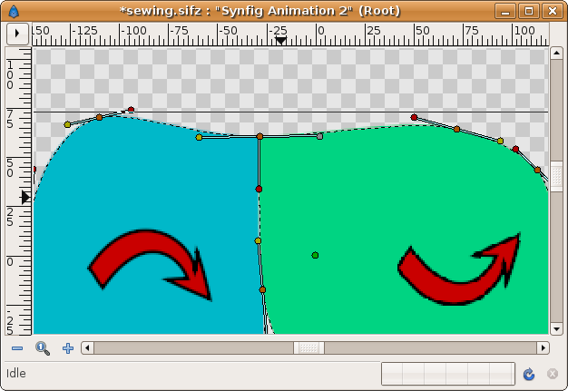
If you're lucky you can link the tangents and the Regions will display properly. In the following example the direction of region construction is shown by the red arrow. You can see that the yellow tangent Handles are on the same side of the vertex (the orange Handles). Similarly with the red Handles. It is not so obvious when the tangents are not parallel.
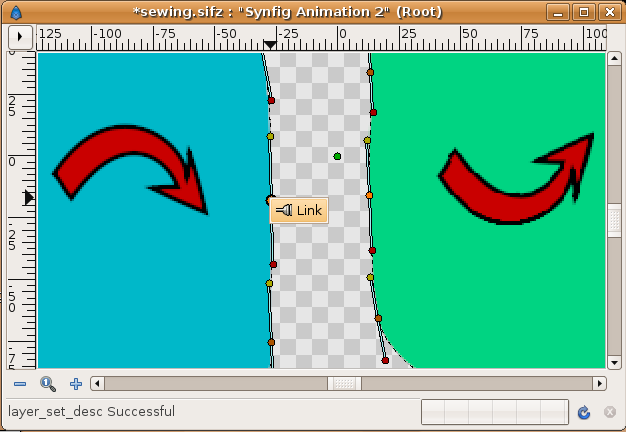
Select the vertex Handles, right click and select the context menu "Link"
Then repeat the same procedure with the tangents (only one of the pairs of tangents needs linking unless the tangents are split)
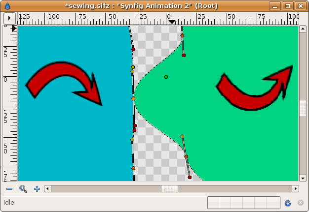
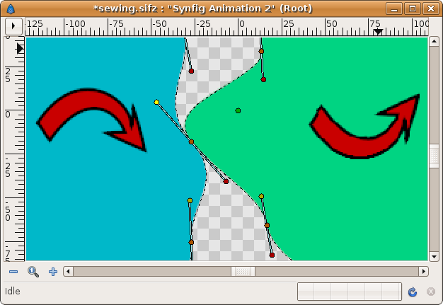
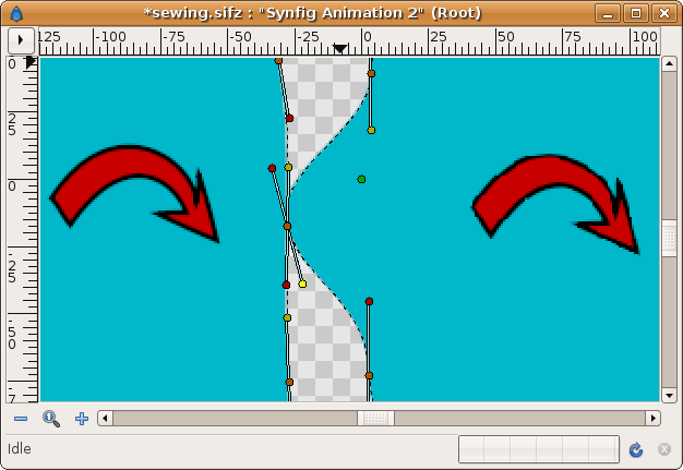
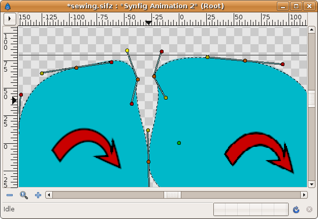
Now watch this situation. The Regions are constructed with the same clockwise direction. The result is that the shared edge become incompatible for linking properly. The tangents are opposite each other (its yellow or red Handles are not at the same side of the vertex Handle).
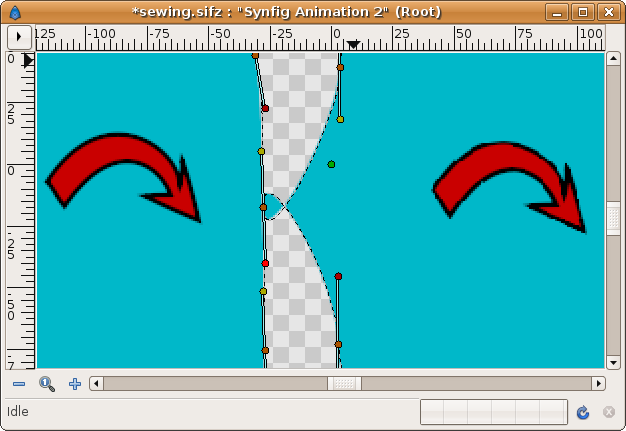
Repeat the same steps as before. First link the vertex Handles and then link the tangent Handles. No matter what tangent Handles you link together (same color or different color), it always gives the same result:
Solution
To solve this problem there is a smart solution. Since the tangents of each Spline are placed opposite each other, the solution comes from converting one of the tangents to a scaled one. The scale should be exactly -1. This allows us to link opposite tangents together since we are going to link one of the tangents to the other tangent, but this last one would be displayed as its inverse by the scale conversion (so the Spline has not the loop when rendered).
(Recently has been commited a new convert type Reverse Tangent
which might allow simplification of this task, but it's not yet clear whether that's the case.)
In the example, let's chose to make the right Region the one that we are going to modify with the scale conversion. Here are the steps you should perform before you link the tangents. You can do it later but should repeat the linking operations.
- Select the vertex from the vertices list in the Parameter Panel. It will be marked with a red square around it in the WorkArea.
- Open the Vertex definition and search for the tangent you want to modify. If they are merged you can do it with either of them.
- Right click and select Convert->Scale
- Open the converted tangent and see that there are two new parameters: "Link" and "Scale".
- Right click over the "Link" parameter and Export it giving a proper name (for example 't4' if it is the vertex number 4)
- Go to the Library Panel and select the Value node you just have exported.
- Now go to the other layer and search the tangent you want to link to.
- Select it, right click, and select the "Connect" option.
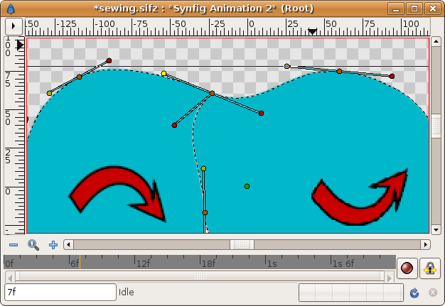
- Now you have obtained the same result as before!! :(. The Regions are looped at that point!!. Here comes the trick. :)
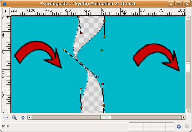
- Go to the converted and exported tangent, find the "Scale" parameter you have obtained from the Scale conversion, and set it to -1. Voila! the tangents match each other!
Alternatively, instead of converting to Scale and exporting the Link you could
convert to Reverse Tangent and link it directly. I have not tested yet.
Notice that the other vertex Handles (of the other vertices) show how they have opposite colors.
Drawbacks
The converted tangents lose the ability to being manipulated by tangents Handles since the tangent is no longer a Radial Composite value node which is the type of conversion that Synfig knows how manage internally with Handles interface.
You should modify the tangent of the vertex of that Region using the Handles of the other Region Layer or by the numerical input of the x,y values.
Sewing more than two Splines
Sewing more than two Splines is much the same as the case described because locally you are only going to stitch two tangents each time. If you need to sew more than one vertex at the same place just repeat the steps making the proper change of tangent sign as appropriate.
Sewing corners
One not obvious situation happen when you have to sew two corners. In that case the tangents (almost one of them) must be split. It can happen two clearly different situations:
- The outside tangents are linked. Usually you link them to obtain an smooth surface. It is like a 180 DEG corner.
- The outside tangents aren't linked. Then you want to create a real corner with control of each tangent. This case is a particular case of the above.
So lets study the case where the outside tangents are going to be linked having opposite values (they are always 180 DEG separated).
That case can be reached by two regions with same clockwise construction or opposite. Let start with the simple one.
Creating a smooth corner for compatible Splines
When you want to link two vertices that are going to create a smooth corner (a 180 DEG one) you have to do the following (I assume that the vertices are already linked, if not you can do it now or later):
- As well as the regions are tangent compatible (see the first previous example) the tangent Handles have same color on same side of the vertex. First is to split the tangents of both vertices. Right click on vertex and "Split Tangents".
- Then you should directly link the two tangents Handles for the inner par of the corner. It is the tangent that points down in the following figure (the red ones)
- If you link the other two tangents (the yellow ones) you would obtain two identical tangents. That's not what we ant to achieve we want that both tangents have the opposite direction so they match smoothly.
- Repeat the steps of Convert->Scale, export "Link" parameter, link the exported to the other tangent and set "Scale" parameter to be -1. It would allow obtain this figure.
There you can see that the one of the two Handles of the upper tangent is greyed. It means that it cannot be manipulated due it is the one what was converted to "Scale". To manipulate that tangent you must use the left side Handle.
The red ones Handles of the other tangent are overlapping and you can manage one of them at a time.
If you don't want to create an smooth corner just don't make the link of the yellow tangent Handles in this case. Set them free and make the corner you want.
Creating a smooth corner for not compatible Splines
If the SpLines are not compatible (second example of above) you should make now only one conversion too. The inner tangent still not being compatible, so it need a conversion to Scale, an export, a link to the other tangent and a Sсale set to -1, like in the previous example. But the outer one is compatible now because they are already two inverted tangents and can be linked to create a 180 DEG corner.
So after you have split the tangents you should obtain something like this:
Now, you should link the left red Handle with the right yellow one but they are opposite tangents (opposite colors). Then convert one of them (the yellow one in the example) to scale, export the "Link" parameter, link it to the other (red) tangent Handle and make the Scale parameter to be -1. It will make both regions have same rendered tangent on the sharing edge.
Once done, you simply need to join the two upper Handles (yellow left and red right). As well they are opposite they are compatible for a 180 DEG corner. The result should be this:
Dead End Corner
(If anyone has a better name for this kind of meeting of vertices please change it freely)
I gave this name to a a vertex that is completely surrounded by Splines so that it doesn't have any outside tangent. The inner vertex of a shared edge is the extreme example of the most general case of a Dead End Corner vertex. It has only two tangents.
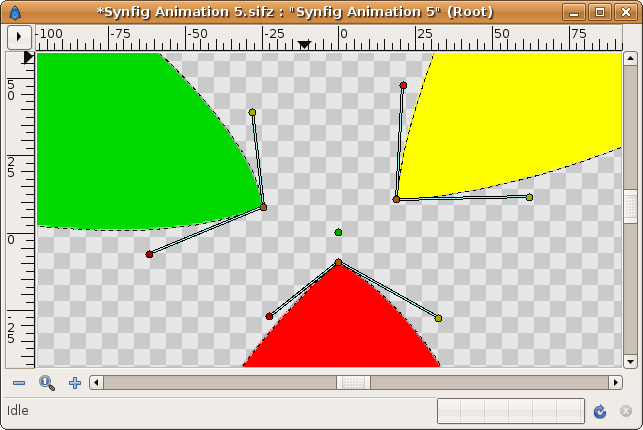
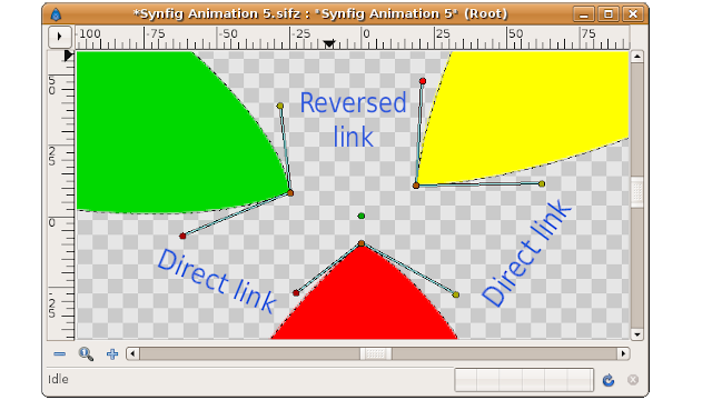
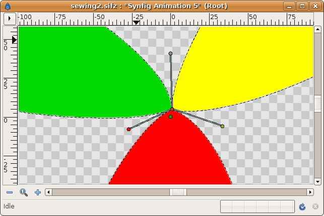
Here is an example of a preparation of a Dead End Corner. The three Regions are going to be joined at the central vertex.
If you have a look at the tangent Handles you can see that they match in pairs except the two upper ones. If you have followed the tutorial you can easily imagine that the tangent Handles that have matching colors can be linked directly and the ones that mismatch should be converted to scale, have their "Link" parameter exported, linked to the other tangent, and set the Scale parameter to -1. Like this:
So making the direct linking of the lower tangent Handles and making a reversed link to the upper pair of tangent Handles the Dead End Corner is properly created. Please try it for yourself. If you have problems, please ask here in this article's Talk page.
Here is the result:
Removing thin line bug
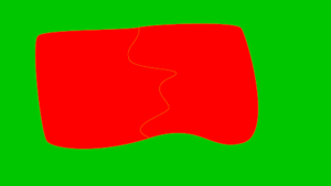
There is a not solved "bug" that makes thin lines when you sew regions with same color. It is only a pixel thick. This is "not really" a bug. Such behaviour is caused by the way how anti-aliasing works in the Synfig's rendering engine.To workaround this "not really" bug meanwhile it is solved you can do one of the following:
- For each layer is affected, create a outline layer using same color than the region. Then select both layers and make right click over the "Vertices" paramter (greyed) then select "Link". Set the outline width to 1.0. It will be enough to remove the think line.
- Add a super sample layer and set its value to 3x3 or 4x4 to eliminate the thin line.
- If the regions are outlined but not in the area of the thin line, you can uncheck the antialiasing parameter and the thin line would disappear.
