Basic Bone Tutorial
(Copie of english version before to translate) |
m (2 first paragraphs) |
||
| Line 12: | Line 12: | ||
<br clear=all> | <br clear=all> | ||
== Introduction == | == Introduction == | ||
| − | + | Dans ce tutoriel nous allons doter un bras d'une armature avec des jointures fixes en utilisant le{{l|Skeleton Layer}} et 3 os (bones). Le bras est constitué de 3 parties: '''upperArm''', '''lowerArm''' et '''hand'''. (pic.1) Chaque partie est groupée dans son propre calque et les trois groupes sont eux-mêmes groupés dans un calque appelé '''arm''' (pic.2). | |
| − | [[File:bonestut01.png|left|frame| | + | [[File:bonestut01.png|left|frame|IMAGE 1: Les trois parties du bras]] [[File:bonestut09.png|centre|frame|216x475px|IMAGE 2: Les calques]] |
<br clear=all> | <br clear=all> | ||
| − | == | + | == Préparation des jointures == |
| − | [[File:bonestut02.png|left|200x237px|frame| | + | [[File:bonestut02.png|left|200x237px|frame|IMAGE 3: Jointures]] |
| − | + | Avant de commencer à doter le bras d'une armature nous devons le préparer afin d'être sûr que les jointures tourneront correctement. Dans ''image 1'' nous pouvons voir que la partie basse du haut du bras est droit et ne possède pas de bordure, alors que la partie haut de l'avant-bras possède une bordure qui est courbe. La parite basse de l'avant bras n'a pas de bordure et est également droite. LA jointure de la main est également courbe avec une bordure. Pour s'assurer que le parties de jointures du bras tournent correctement, nous les avons faites avec l'aide de quelques croix de visée (ou crosshair, image 3). Dans ''image 4'' et ''image 5'' nous pouvons voir comment la ligne horizontale du crosshair correspond à la ligne droite du bas de la partie haute du bras et en même temps la bordure du cercle du crosshair correspond à la bordure incurvée supérieure de l'avant-bras. Le même principe est appliqué à la main et à la partie basse de l'avant-bras. Les crosshairs marquent aussi le centre du point de rotation qui sera utilisé ultérieurement durant le placement des armatures. Avant de placer les armatures nous pouvons aligner le {{l|Group Transformation Widget}} (pressez contrôle et tirez la poignée du coin gauche du {{l|Group Transformation Widget}} pour le déplacer.) du groupe '''lowerArm''' et le groupe '''hand''' avec les crosshairs du coude et le poignet pour vérifier si les jointures tournent correctement. N'oubliez pas d'amener le bras dans sa position initiale originale en pressnt undo. (Ne vous inquiétez pas si la main ne tourne pas avec le coude quand vous vérifierez la jointure du coude en utilisant le {{l|Group Transformation Widget}}.) | |
<br clear=all> | <br clear=all> | ||
| − | [[File:bonestut07.png|left|frame| | + | [[File:bonestut07.png|left|frame|IMAGE 4: Alignement des jointures]] [[File:bonestut08.png|center|frame|IMAGE 5: Aligment des jointures]] |
<br clear=all> | <br clear=all> | ||
Revision as of 23:01, 15 August 2015
Introduction
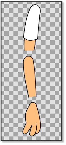
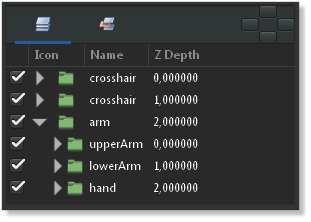
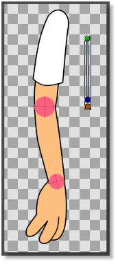
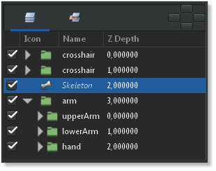
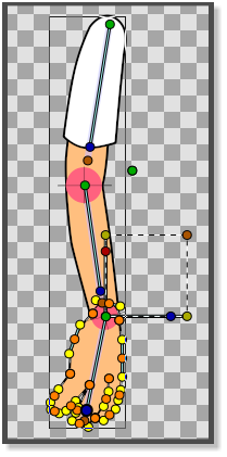
Dans ce tutoriel nous allons doter un bras d'une armature avec des jointures fixes en utilisant leSkeleton Layer et 3 os (bones). Le bras est constitué de 3 parties: upperArm, lowerArm et hand. (pic.1) Chaque partie est groupée dans son propre calque et les trois groupes sont eux-mêmes groupés dans un calque appelé arm (pic.2).
Préparation des jointures
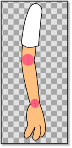
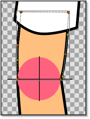
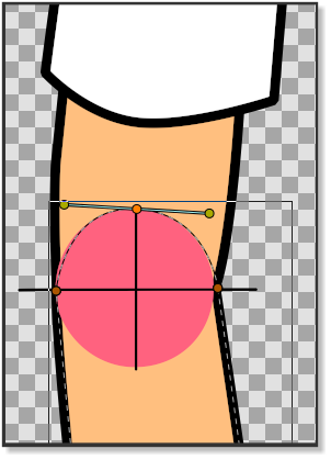
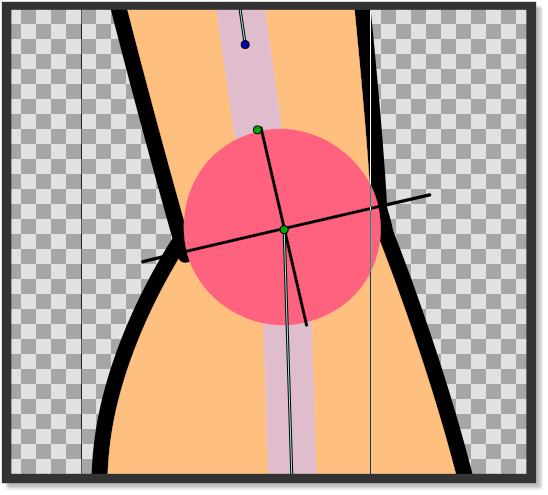
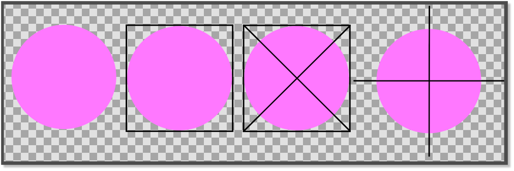
Avant de commencer à doter le bras d'une armature nous devons le préparer afin d'être sûr que les jointures tourneront correctement. Dans image 1 nous pouvons voir que la partie basse du haut du bras est droit et ne possède pas de bordure, alors que la partie haut de l'avant-bras possède une bordure qui est courbe. La parite basse de l'avant bras n'a pas de bordure et est également droite. LA jointure de la main est également courbe avec une bordure. Pour s'assurer que le parties de jointures du bras tournent correctement, nous les avons faites avec l'aide de quelques croix de visée (ou crosshair, image 3). Dans image 4 et image 5 nous pouvons voir comment la ligne horizontale du crosshair correspond à la ligne droite du bas de la partie haute du bras et en même temps la bordure du cercle du crosshair correspond à la bordure incurvée supérieure de l'avant-bras. Le même principe est appliqué à la main et à la partie basse de l'avant-bras. Les crosshairs marquent aussi le centre du point de rotation qui sera utilisé ultérieurement durant le placement des armatures. Avant de placer les armatures nous pouvons aligner le Group Transformation Widget (pressez contrôle et tirez la poignée du coin gauche du Group Transformation Widget pour le déplacer.) du groupe lowerArm et le groupe hand avec les crosshairs du coude et le poignet pour vérifier si les jointures tournent correctement. N'oubliez pas d'amener le bras dans sa position initiale originale en pressnt undo. (Ne vous inquiétez pas si la main ne tourne pas avec le coude quand vous vérifierez la jointure du coude en utilisant le Group Transformation Widget.)
Adding the bones
Now it’s time to add a Skeleton Layer that will provide the bones we need to rig the arm.
Right-click on any layer in the Panneau Calques and choose "<New Layer> → <Other> → <Skeleton>". A new Skeleton Layer (pic. 7) will appear in the Panneau Calques alongside with a small bone in the canvas (pic.6). Put the Skeleton Layer above the arm group if it is not already there. The green handle of the bone is the origin of the bone and is used to move the bone in place and is also its centre of rotation. The blue handle is used to rotate the bone. The orange handle determines the lenght of the bone is used to stretch the bone and its contents. The first bone is the parent bone and should be moved toward the shoulder and stretched so that it almost reaches the outlines of the first crosshair of the elbow. Right-click on any of the handles of the parent bone and select "Create Child Bone". Move the green origin point of the child bone so that it matches the crosshair of the elbow and stretch it until it almost reaches the crosshair of the wrist. Right click on any of the handles of the child bone and create another child bone. Move the green origin point of the second child bone so that it matches the crosshair of the wrist (pic.8). Stretch the bone until it reaches the end of the fingers.
Attaching the bones
Now that the Skeleton Layer is in place we have to attach the bones to the parts of the arm. In the Panneau Calques click on the upperArm group, right-click and "Select All Child Layers". Then press CtrlA in the canvas window. With everything in the upperArm group highlighted, Ctrl-click on any bone in the canvas window and right-click on any of the handles of the parent bone and click "Link to Bone". The upperArm group is now linked to the parent bone. Go the Panneau Calques again and select the lowerArm group. Right-click and "Select All Child Layers". Press CtrlA in the canvas window and Ctrl-click on one of the bones. Then right-click on any of the handles of the first child bone and select "Link to bone". The lowerArm group is now linked to the second child bone. In the Panneau Calques select all the child layers of the hand group and press CtrlA in the canvas window. Ctrl-click on any bone and then right-click on any of the handles of the second child bone and select "Link to bone" (pic.8) The hand is now linked to the second child bone and the entire skeleton is now linked to the arm.
The sif file containing the parts of this tutorial can be found here
Tip
Making a crosshair in Synfig is easy. Draw a circle. Draw the outlines of a square and align them with the circle. Draw an X using the corners of the square as a reference. Delete the square. Group the circle and the X. Rotate 45 degrees using the Group Transformation Widget.

