Basic Bone Tutorial
Introduction
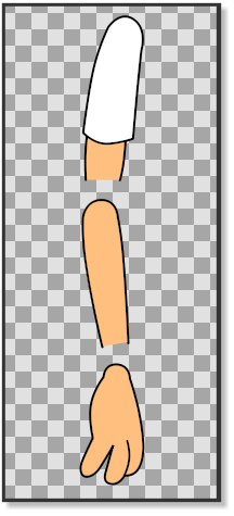
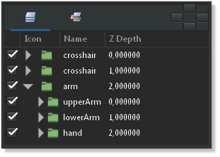
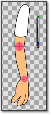
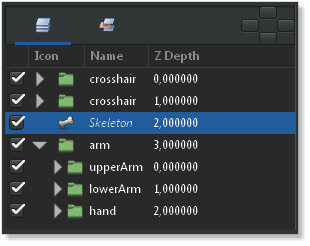
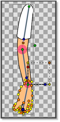
In this tutorial we are going to rig an arm with fixed joints using the Skeleton Layer and three bones. The arm consists of three parts: the upperArm, the lowerArm and the hand. (pic.1) Each part is grouped in its own layer and the three groups are again grouped in a layer that is called arm (pic.2).
Prepare the joints
Before we start rigging the arm we have to prepare it to make sure that the joints properly rotate.
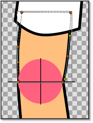
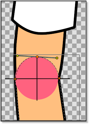
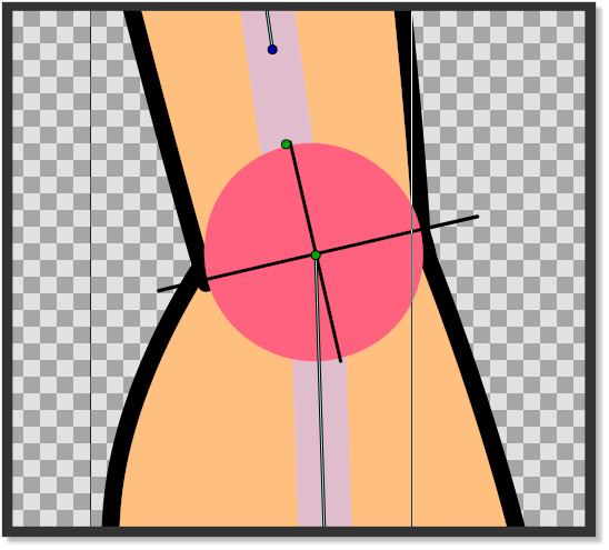
In picture 1 we can see that the lower side of the upper arm is straight and does not have an outline, while the upper part of the lower arm has an outline that is curved. The bottom part of the lower arm does not have an outline and is also straight. The joint of the hand is also curved with an outline.
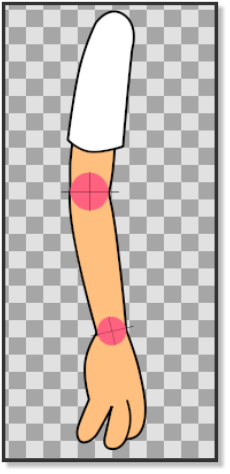
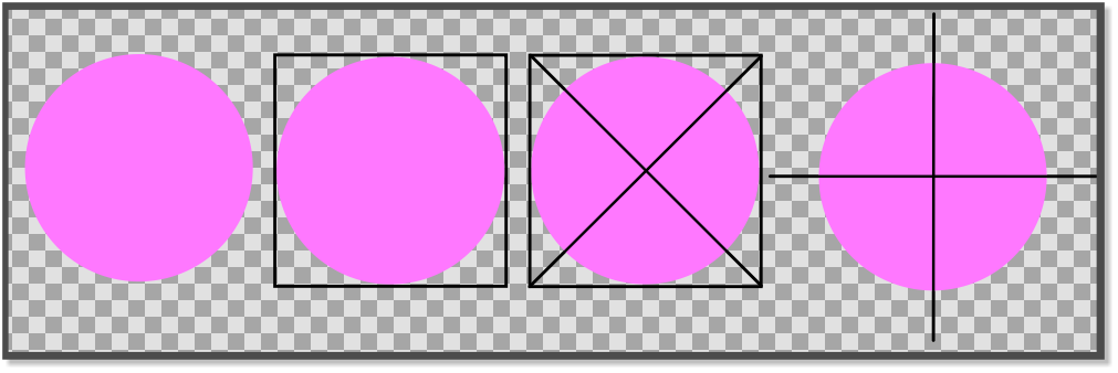
To make sure that the joint parts of the arm rotate correctly, we made them with the help of a couple of crosshairs (picture 3). In picture 4 and picture 5 we can see how the horizontal crosshair line matches the straight line of the bottom of the upper arm and at the same time the outline of the circle of the crosshair matches the top curved outline of the lower arm.
The same principle is applied to the hand and the bottom part of the lower arm. The crosshairs also mark the centre of the rotation point that will later be used when placing the bones. Before placing the bones we can align the Group Transformation Widget (press control and move the left corner handle of the Group Transformation Widget to move it.) of the lowerArm group and the hand group with the crosshairs of the elbow and the wrist to check if the joints rotate correctly.
Don’t forget to bring the arm into its original position by pressing undo. (Don’t worry if the hand does not rotate with the elbow when you check the elbow joint by using the Group Transformation Widget.)
Adding the bones
Now it’s time to add a Skeleton Layer that will provide the bones we need to rig the arm.
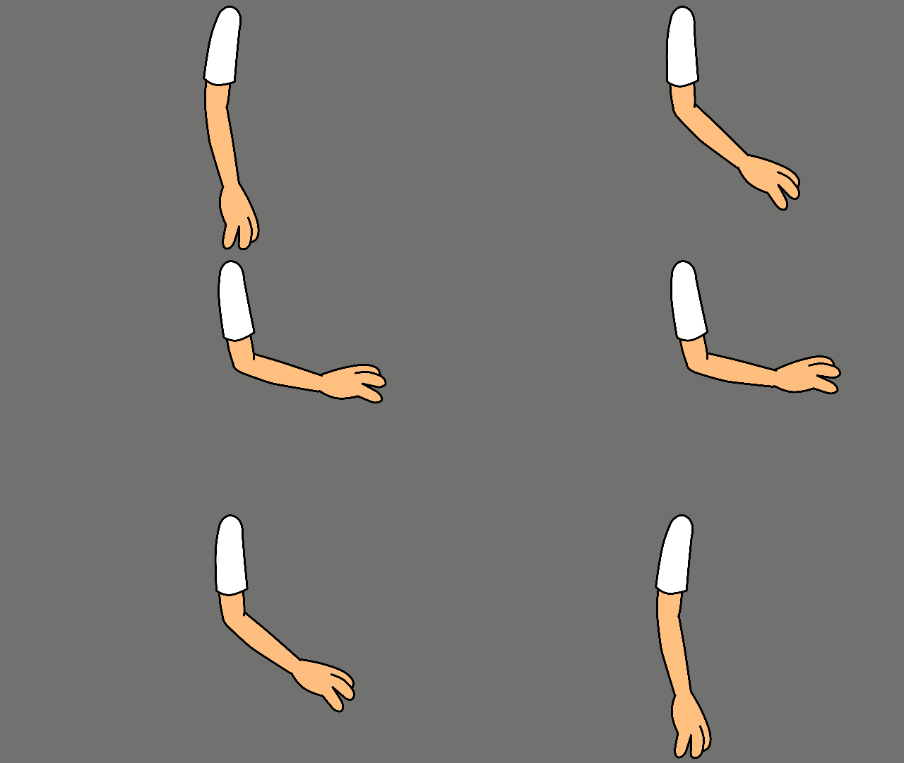
Right-click on any layer in the Layers Panel and choose "<New Layer> → <Other> → <Skeleton>". A new Skeleton Layer (pic. 7) will appear in the Layers Panel alongside with a small bone in the canvas (pic.6). Put the Skeleton Layer above the arm group if it is not already there. The green handle of the bone is the origin of the bone and is used to move the bone in place and is also its centre of rotation. The blue handle is used to rotate the bone. The orange handle determines the lenght of the bone is used to stretch the bone and its contents. The first bone is the parent bone and should be moved toward the shoulder and stretched so that it almost reaches the outlines of the first crosshair of the elbow. Right-click on any of the handles of the parent bone and select "Create Child Bone". Move the green origin point of the child bone so that it matches the crosshair of the elbow and stretch it until it almost reaches the crosshair of the wrist. Right click on any of the handles of the child bone and create another child bone. Move the green origin point of the second child bone so that it matches the crosshair of the wrist (pic.8). Stretch the bone until it reaches the end of the fingers.
Attaching the bones
Now that the Skeleton Layer is in place we have to attach the bones to the parts of the arm.
In the Layers Panel click on the upperArm group, right-click and "Select All Child Layers". Then press CtrlA in the canvas window. With everything in the upperArm group highlighted, Ctrl-click on any bone in the canvas window and right-click on any of the handles of the parent bone and click "Link to Bone". The upperArm group is now linked to the parent bone. Go the Layers Panel again and select the lowerArm group. Right-click and "Select All Child Layers". Press CtrlA in the canvas window and Ctrl-click on one of the bones. Then right-click on any of the handles of the first child bone and select "Link to bone". The lowerArm group is now linked to the second child bone. In the Layers Panel select all the child layers of the hand group and press CtrlA in the canvas window. Ctrl-click on any bone and then right-click on any of the handles of the second child bone and select "Link to bone" (pic.8).
The hand is now linked to the second child bone and the entire skeleton is now linked to the arm.
It is worth to note for new users that in case the bone is linked to an image, selecting all its handles and linking them to the bone could lead to an initially unpredictable behavior. If we need for example to apply only a rotation around the pivot point defined by the bone, it is necessary to select only the green handle that defines its position. Then use the blue handle of the bone to apply the rotation.
Tip for making a crosshair
Making a crosshair in Synfig is easy. Draw a circle. Draw the outlines of a square and align them with the circle. Draw an X using the corners of the square as a reference. Delete the square. Group the circle and the X. Rotate 45 degrees using the Group Transformation Widget.
Project file
The sif file containing the parts of this tutorial can be found here
Explanation n°2 additional
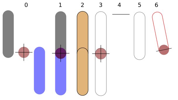
To transform 2 sticks into 1 leg
The top stick is a "thigh", the bottom stick is a calf.
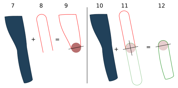
- 0: 2 identical sticks + a crosshair.
- 1: The 2 sticks touch edge to edge to form a crosshair.
- 2: The 2 sticks without crosshair of flesh color.
- 3: The 2 sticks with crosshair without color.
- 4: This mark must be used.
- 5: To cut the upper limb.
- 6: Like here.
- 7: Then the limb must be merged (full).
- 8: With the cut part.
- 9: Result.
- 10: Same for bottom limb.
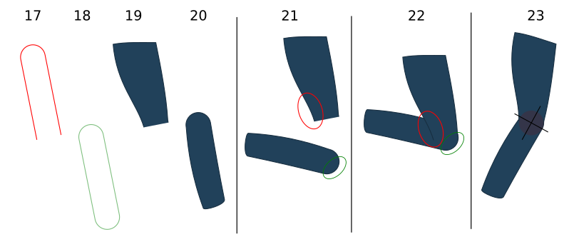
- 13: The only part not to be merge is the one where the circle (blue) it is the crosshair that should not be touched.
- 15: Then the rotation will be correct.
- 16: To be able to do any rotation.
- 17: Limb of the top.
- 18: Limb of the bottom.
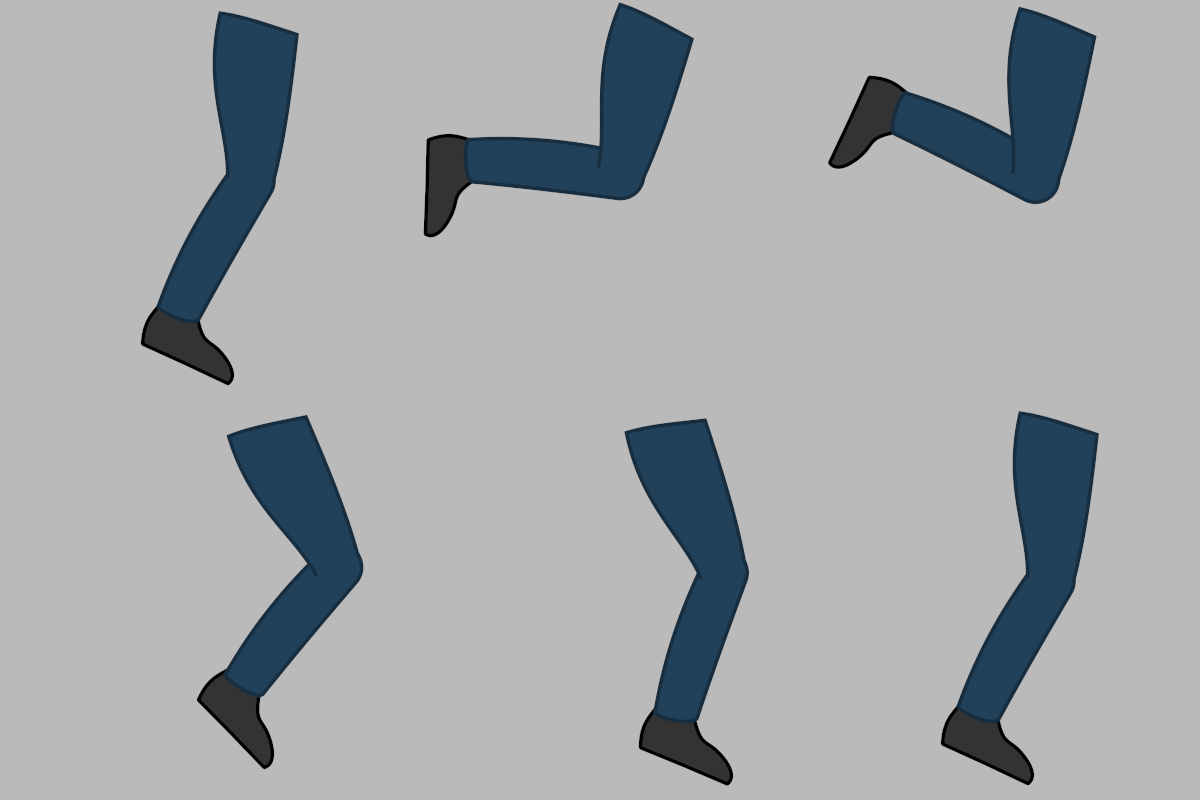
- 21: Limbs in movement (detached).
- 22: Limbs in movement (attached).
- 23: The leg finished with the crosshair.
Important
The crosshair must stay with our 2 sticks, for the duration of the limb's creation.
Project File
The zip file containing the parts of this tutorial can be found here: Crosshair-leg.zip
Next Steps
This is the end of the introductory tutorials. From here you can take a look at the Interface page, or continue reading or doing the rest of Tutorials. The Manual gives you a list of the available articles to read for a more complete understanding of Synfig.
