Sewing BLines
(→Definirea problemei) |
(→Solution) |
||
| Line 34: | Line 34: | ||
{{l|Image:Link5.png}} | {{l|Image:Link5.png}} | ||
| − | == | + | == Solutie == |
| − | + | Pentru a rezolva aceasta problema exista o solutie simpla. Atata timp cat tangentele fiecarei Bline sunt asezate in sens opus una alteia, solutia este de a converti una dintre tangente prin scalarea ei. Scala trebuie sa fie de exact -1. Acest lucru ne permite sa legam impreuna tangentele opuse. | |
| − | ( | + | (Recent a aparut un nou tip de conversie - {{l|Convert#Reverse Tangent|Reverse Tangent}} |
| − | + | care se pare ca simplifica aceasta operatiune.) | |
| − | In | + | In exemplu, let's chose to make the right Region the one that we are going to modify with the scale conversion. Here are the steps you should perform before you link the tangents. You can do it later but should repeat the linking operations. |
# Select the vertex from the vertices list in the Parameter Dialog. It will be marked with a red square around it in the workarea. | # Select the vertex from the vertices list in the Parameter Dialog. It will be marked with a red square around it in the workarea. | ||
Revision as of 14:21, 19 April 2012
|
Warning! This page contains outdated information. The release of Synfig Studio 0.64.0 introduced new terminology and this translated page needs to be updated according to original English text. You can help updating this page - see instructions here. Thank you! |
Aceasta este o lectie scurta in care se descrie cum se pot uni straturile bazate pe obiecte BLine dupa marginile acestora. Astfel de straturi includ straturile regiune - Region Layers, straturile contur - Outline Layers, straturile Plant Layer si stratul Curve Gradient Layer.
Contents
Definirea problemei
Nu este posibil sa se poata lega marginile BLines, deoarece in unele cazuti acestea sunt construite in directii opuse (sens orar si antiorar=trigonometric), din aceasta cauza tangentele nu sunt potrivite pentru legarea uneia cu alta.
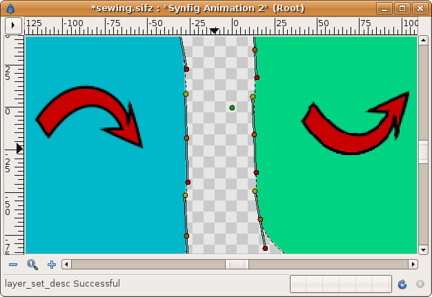
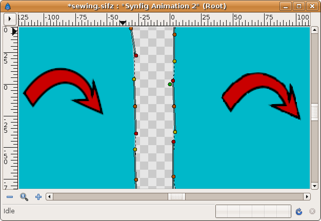
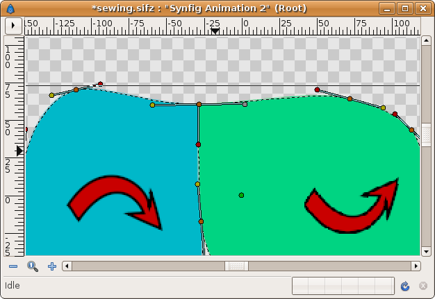
In cazul in care aveti noroc, cand legati tangentele si regiunile, acestea vor fi afisate corespunzator. In exemplul urmator, directia constructiei regiunii este desenata cu o sageata rosie. Puteti vedea ca marcatorii tangenti de culoare galbena sunt de aceeasi parte a nodului (marcatorii portocalii). La fel si cu marcatorii rosii. Acest lucru nu este atât de evident atunci când tangentele nu sunt paralele
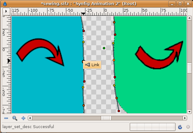
Selectati marcatorii nodului si cu click-buton-dreapta selectati "Link" din meniul contextual.
Apoi repetati aceeasi procedura cu tangentele (doar una din perechea de tangente trebuie sa fie legata, cu exceptia cazului in care tangentele sunt despartite - split)
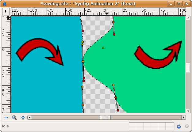
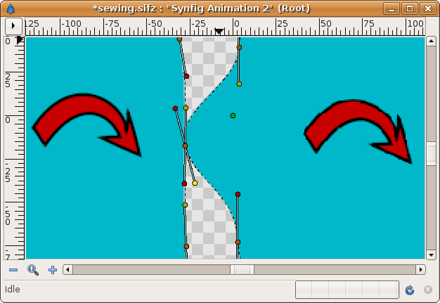
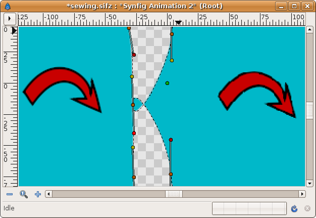
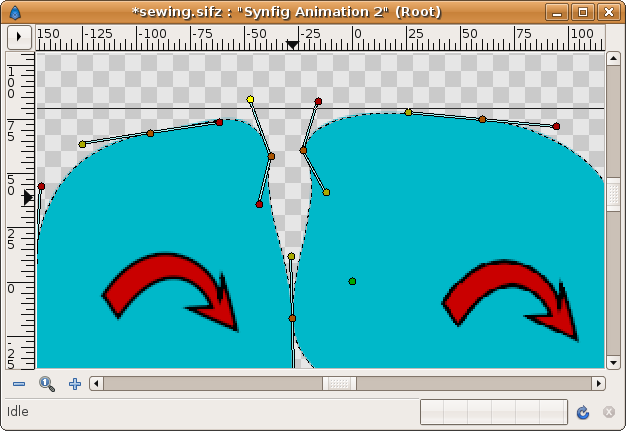
Acum sa observam aceasta situatie. Regiunile sunt construite in sens orar. Rezultatul este ca marginea in comun devine incompatibila pentru legarea corespunzatoare. Tangentele sunt opuse una alteia (marcatorii galbeni sau rosii nu se afla pe aceeasi parte a marcatorului nodului).
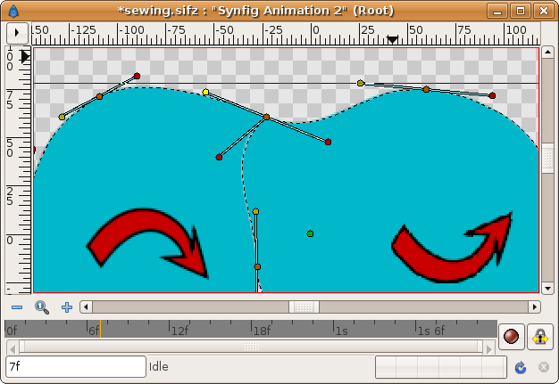
Repetati etapele ca mai sus. Mai intai legati marcatorii nodului, apoi legati marcatorii tangentei. Nu conteaza ce marcatori de tangenta legati impreuna (aceeasi culoare sau culori diferite), veti obtine mereu acelasi rezultat:
Solutie
Pentru a rezolva aceasta problema exista o solutie simpla. Atata timp cat tangentele fiecarei Bline sunt asezate in sens opus una alteia, solutia este de a converti una dintre tangente prin scalarea ei. Scala trebuie sa fie de exact -1. Acest lucru ne permite sa legam impreuna tangentele opuse.
(Recent a aparut un nou tip de conversie - Reverse Tangent
care se pare ca simplifica aceasta operatiune.)
In exemplu, let's chose to make the right Region the one that we are going to modify with the scale conversion. Here are the steps you should perform before you link the tangents. You can do it later but should repeat the linking operations.
- Select the vertex from the vertices list in the Parameter Dialog. It will be marked with a red square around it in the workarea.
- Open the Vertex definition and search for the tangent you want to modify. If they are merged you can do it with either of them.
- Right click and select Convert->Scale
- Open the converted tangent and see that there are two new parameters: Link and Scale.
- Right click over the Link parameter and Export it giving a proper name (for example 't4' if it is the vertex number 4)
- Go to the Child list and Select the Value node you just have exported.
- Now go to the other layer and search the tangent you want to link to.
- Select it, right click, and select the Connect option.
- Now you have obtained the same result as before!! :(. The Regions are looped at that point!!. Here comes the trick. :)
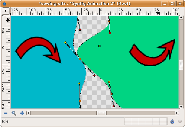
- Go to the converted and exported tangent, find the Scale parameter you have obtained from the Scale conversion, and set it to -1. Voila! the tangents match each other!
Alternatively, instead of converting to Scale and exporting the Link you could
convert to Reverse Tangent and link it directly. I have not tested yet.
Notice that the other vertex ducks (of the other vertices) show how they have opposite colors.
Drawbacks
The converted tangents lose the ability to being manipulated by tangents ducks since the tangent is no longer a Radial Composite value node which is the type of conversion that Synfig knows how manage internally with ducks interface.
You should modify the tangent of the vertex of that Region using the ducks of the other Region layer or by the numerical input of the x,y values.
Sewing more than two Blines
Sewing more than two Blines is much the same as the case described because locally you are only going to stitch two tangents each time. If you need to sew more than one vertex at the same place just repeat the steps making the proper change of tangent sign as appropriate.
Sewing corners
One not obvious situation happen when you have to sew two corners. In that case the tangents (almost one of them) must be split. It can happen two clearly different situations:
- The outside tangents are linked. Usually you link them to obtain an smooth surface. It is like a 180 DEG corner.
- The outside tangents aren't linked. Then you want to create a real corner with control of each tangent. This case is a particular case of the above.
So lets study the case where the outside tangents are going to be linked having opposite values (they are always 180 DEG separated).
That case can be reached by two regions with same clockwise construction or opposite. Let start with the simple one.
Creating a smooth corner for compatible Blines
When you want to link two vertices that are going to create a smooth corner (a 180 DEG one) you have to do the following (I assume that the vertices are already linked, if not you can do it now or later):
- As well as the regions are tangent compatible (see the first previous example) the tangent ducks have same color on same side of the vertex. First is to split the tangents of both vertices. Right click on vertex and "Split Tangents".
- Then you should directly link the two tangents ducks for the inner par of the corner. It is the tangent that points down in the following figure (the red ones)
- If you link the other two tangents (the yellow ones) you would obtain two identical tangents. That's not what we ant to achieve we want that both tangents have the opposite direction so they match smoothly.
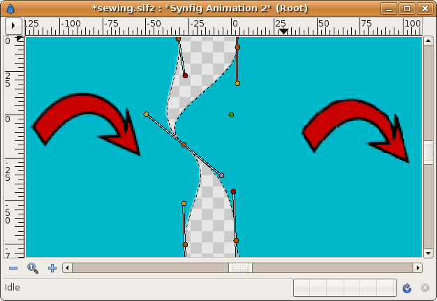
- Repeat the steps of Convert->Scale, export Link parameter, link the exported to the other tangent and set Scale parameter to be -1. It would allow obtain this figure.
There you can see that the one of the two ducks of the upper tangent is greyed. It means that it cannot be manipulated due it is the one what was converted to Scale. To manipulate that tangent you must use the left side duck.
The red ones ducks of the other tangent are overlapping and you can manage one of them at a time.
If you don't want to create an smooth corner just don't make the link of the yellow tangent ducks in this case. Set them free and make the corner you want.
Creating a smooth corner for not compatible Blines
If the BLines are not compatible (second example of above) you should make now only one conversion too. The inner tangent still not being compatible, so it need a conversion to Scale, an export, a link to the other tangent and a Sсale set to -1, like in the previous example. But the outer one is compatible now because they are already two inverted tangents and can be linked to create a 180 DEG corner.
So after you have split the tangents you should obtain something like this:
Now, you should link the left red duck with the right yellow one but they are opposite tangents (opposite colors). Then convert one of them (the yellow one in the example) to scale, export the Link parameter, link it to the other (red) tangent duck and make the Scale parameter to be -1. It will make both regions have same rendered tangent on the sharing edge.
Once done, you simply need to join the two upper ducks (yellow left and red right). As well they are opposite they are compatible for a 180 DEG corner. The result should be this:
Dead End Corner
(If anyone has a better name for this kind of meeting of vertices please change it freely)
I gave this name to a a vertex that is completely surrounded by BLines so that it doesn't have any outside tangent. The inner vertex of a shared edge is the extreme example of the most general case of a Dead End Corner vertex. It has only two tangents.
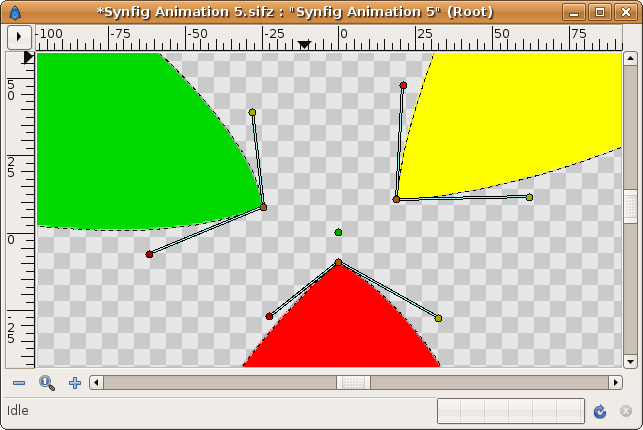
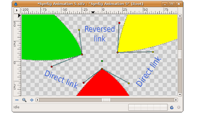
Here is an example of a preparation of a Dead End Corner. The three Regions are going to be joined at the central vertex.
If you have a look at the tangent ducks you can see that they match in pairs except the two upper ones. If you have followed the tutorial you can easily imagine that the tangent ducks that have matching colors can be linked directly and the ones that mismatch should be converted to scale, have their Link parameter exported, linked to the other tangent, and set the Scale parameter to -1. Like this:
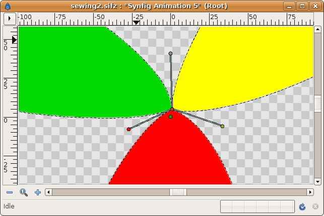
So making the direct linking of the lower tangent ducks and making a reversed link to the upper pair of tangent ducks the Dead End Corner is properly created. Please try it for yourself. If you have problems, please ask here in this article's Talk page.
Here is the result:
Removing thin line bug
There is a not solved yet bug that makes thin lines when you sew regions with same color. It is only a pixel thick.
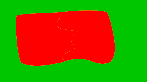
To workaround this bug meanwhile it is solved you can do one of the following:
- For each layer is affected, create a outline layer using same color than the region. Then select both layers and make right click over the Vertices paramter (greyed) then select "Link". Set the outline width to 1.0. It will be enough to remove the think line.
- Add a super sample layer and set its value to 3x3 or 4x4 to eliminate the thin line.
- If the regions are outlined but not in the area of the thin line, you can uncheck the antialiasing parameter and the thin line would disappear.
