Outline Layer
|
Warning! This page contains outdated information. The release of Synfig Studio 0.64.0 introduced new terminology and this translated page needs to be updated according to original English text. You can help updating this page - see instructions here. Thank you! |
Contents
Despre straturile pentru contur
Straturile pentru contur (Outline Layers) sunt folosite pentru a stoca formele create cu instrumentul pensula sau contururile formelor. Acestea dau un aspect de desen animat. Contururile separate (strokes) sunt folosite pentru a defini cute sau desene 3D si sunt sunt adaugate umbrelor (create folosind trecerea de culoare - gradient sau proprietatea feather), constituind baza pentru o lucrare a unui artist.
Pentru a crea un strat pentru contur (Outline Layer) folositi BLine Tool/ro si bifati Create Outline BLine din caseta Tool Options Panel. Dupa ce ati terminat definirea geometriei conturului si dupa ce ati apasat butonul Execute (sau ati selectat alt instrument sau stare) este creat stratul pentru contur, avand culoarea din prim-plan (foreground).
Parametrii straturilor pentru contur
Parametrii straturilor pentru contur sunt (am lasat denumirile in engleza):
| Nume | Valoare | Tip |
| 0.000000 | real | |
| 1.000000 | real | |
| Composite | integer | |
|
|
color | |
| 0.000000u,0.000000u | vector | |
|
|
bool | |
|
|
bool | |
| 0.000000pt | real | |
| Fast Gaussian Blur | integer | |
| Non Zero | integer | |
| List | list (BLine) | |
| 2.000000pt | real | |
| 0.000000pt | real | |
|
|
bool | |
|
|
bool | |
|
|
bool | |
| 1.000000 | real | |
|
|
bool |
Parametri specifici pentru straturile de contur
Primii 11 parametri pentru contur sunt comuni mai multor tipuri de straturi. Click pe legaturi pentru a vedea definitiile acestora. Aici vom descrie doar parametrii specifici pentru stratul de contur.
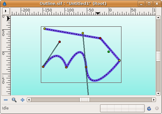
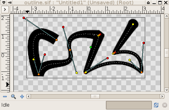
In imaginea de mai jos este prezentat un strat de contur in actiune:
Latimea liniei de contur
Parametrul pentru latimea conturului este o valoare a pixelilor exprimata in zecimale si reprezinta valoarea de baza a latimii pentru toate punctele curbei in acelasi timp. Lucreaza impreuna cu parametrul pentru valorile nodurilor-copil. Setarea latimii conturului la 1.0px da valoarea pentru latimea randata in acel nod cu ajutorul formulei: W = OLW * VW + 2E.
unde:
- W = latimea rezultata a conturului acelui nod.
- OLW = parametrul pentru intreaga latime a nodurilor (acesta este parametrul pentru latimea conturului).
- VW = valoarea latimii specifice a nodului.
- E = valoarea parametrului Expand.
Latimea marcatorului arata valoarea razei acelui nod (W/2).
Latimea la capat, folosita de fiecare nod este ((VertexWidth * OutLineWidth) + Expand*2):
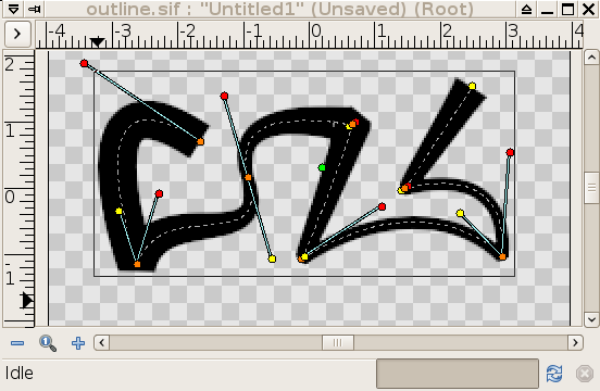
|
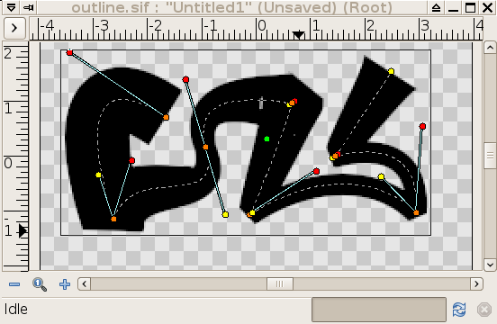
|
| imaginea initiala | dupa dublarea valorii 'latimii conturului' |
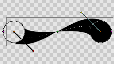
Este posibil sa specificati valori negative pentru latime, in acest caz nodul este "intors pe dos". Iata un exemplu in care nodul din stanga are o latime negativa, iar cel din dreapta o latime pozitiva. Marginile conturului se intersecteaza la mijloc:
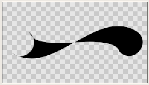
|
|
Expand
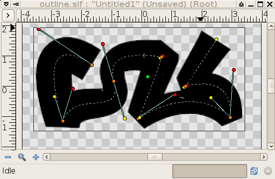
The Expand parameter is similar to the Outline Width parameter, but rather than being multiplied by each vertex's width, it is added to the radius of each vertex. In other words (2*Expand) is added to the diameter of each vertex.
The width that ends up being used for each vertex is ((VertexWidth * OutLineWidth) + Expand*2):

|
|
| zero 'expand' | non-zero 'expand' |
Sharp cups
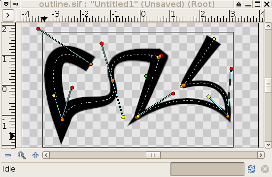
Enabling 'sharp cusps' makes the corners pointy when the tangents are split:

|
|
| no sharp cusps | sharp cusps |
Rounded Begin
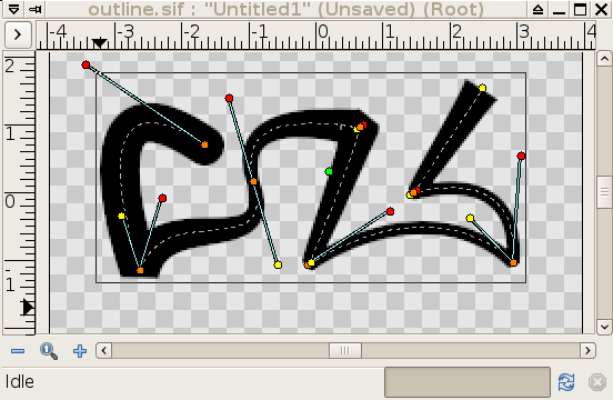
Enabling 'rounded begin' makes the start of the outline rounded:

|
|
| no rounded begin | rounded begin |
Rounded End
Enabling 'rounded end' makes the end of the outline rounded:

|
|
| no rounded end | rounded end |
Loopyness
This parameter currently does absolutely nothing at all!
Homogeneous
Enabling 'Homogeneous' changes the way that the width of the outline changes from one blinepoint to the next. Each point in the bline has its own width, and the bline has its own 'Outline Width' and 'Expand' parameters which are used to give the final width at each blinepoint. The 'Homogeneous' parameter controls how the width is interpolated between two neighbouring blinepoints:
- When 'Homogeneous' isn't checked, the width is interpolated linearly with the spline's 't' parameter.
- When 'Homogeneous' is checked, the width is interpolated linearly with the spline's length.
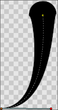
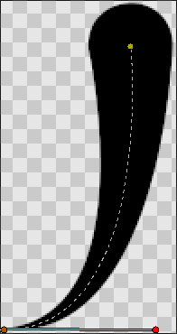
Turning off homogeneous often makes the fat end of a bline look lumpy. Maybe that's a bug:
|
|
| not homogeneous | homogeneous |
Misc
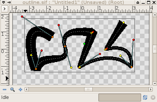
The 'antialias' checkbox isn't specific to the Outline layer, but it is particularly useful for the Outline layer. It makes the edges appear smoother:
|

|
| not antialiased | antialiased |
