Warp Layer/ru
|
Warning! This page contains outdated information. The release of Synfig Studio 0.64.0 introduced new terminology and this translated page needs to be updated according to original English text. You can help updating this page - see instructions here. Thank you! |
Contents
О слоях искажения
Искажение - это простой, но очень мощный инструмент. In a few words it takes a rectangular portion of the resulting render of the layers that are behind it and maps the four corners of the rectangle to four arbitrary points in the plane. It is a 2D -> 2D transformation.
Параметры слоя Искажение
У Искажения есть следующие параметры:
- Источник TL: Координаты верхнего левого угла искажаемой плоскости.
- Источник BR: Координаты нижнего правого угла искажаемой плоскости. Эти две точки определяют прямоугольник области, которая подвергнется искажению.
- Назначение TL: The Top Left corner of the destination where the source is going to be mapped.
- Назначение TR (vertex): The Top Right corner of the destination where the source is going to be mapped.
- Назначение BL (vertex): The Bottom Left corner of the destination where the source is going to be mapped.
- Назначение BR (vertex): The Bottom Right corner of the destination where the source is going to be mapped.
- Обрезка (boolean): Если данная опция включена, то искажаться будет только там часть, которая находится внутри прмоугольника области искажения.
- Горизонт (Real): For infinite layers (gradients, chequerboard, etc.) it define where to stop rendering the points of the vanishing point. From 0.0 to 1.0 it renders all the points that are backwards on the perspective (in opossite direction to the vanishing point). From 1.0 to +infinite it renders the points that go in the same direction of the vanishing point. High values of Horizon make Synfig spend a lot of time rendering and the result is slightly visibly better.
Примеры
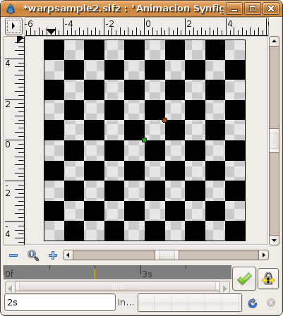
Ниже приведены примеры искажения слоя с клетками (шахматная доска).
До применения искажения:
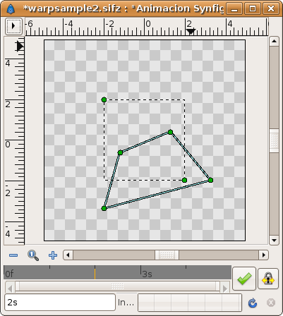
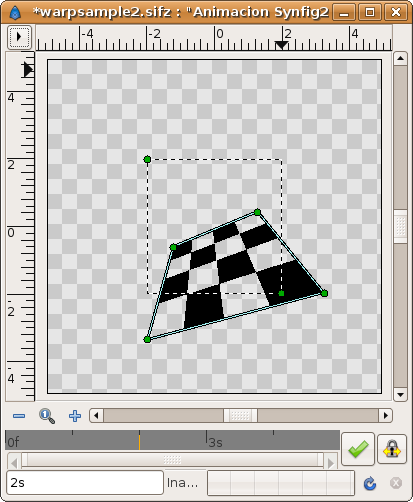
Слой искажения. Пунктиром отмечен прмоугольник, который подвергнется искажению. Параллелепипед из 4 точек это форма накладываемого искажения.
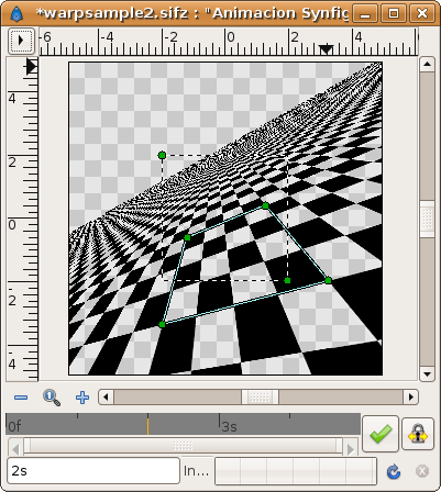
Результат (Горизонт = 15.0; Обрезка выключена). The destination rectangle can be seen to contain the same 4 by 4 section of the checkerboard that the source rectangle contains:
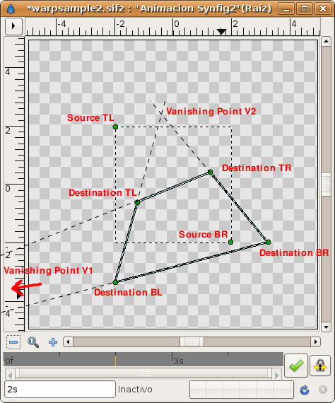
You can see that the rendered horizon is the result of connecting the two vanishing points of the perspective distortion. In this case there are two vanishing points given by the intersection of the lines that connects the following points:
- Intersection of the line that passes by Destination TL point and Destination TR point with the line that passes by Destination BL point and Destination BR point. It gives vanishing point V1 (not shown in the diagram because it is outside the visible area, far off to the left).
- Intersection of the line that passes by Destination TL point and Destination BL point with the line that passes by Destination TR point and Destination BR point. It gives vanishing point V2
Connecting the Vanishing points V1 and V2 gives the horizon line.
See the diagram:
To understand how the Horizon parameter works see this animated image. It moves the Horizon parameter from 0.0 to 30 in four seconds. Notice that from horizon = 0.0 to 1.0 it renders from minus infinite to the current observer position (it is made very fast in the animation, and takes about in 4/30 seconds and most of the time the rendered section is outside the visible area of the canvas - you can see it if you place a zoom out layer on top of them). This means that the portion of plane that is behind the observer point of view is rendered deformed and then very enlarged). Notice too that from horizon = 1.0 to 30.0 it renders the rest of the visible plane. As the horizon parameter gets larger, the final visible horizon gets further away.
Обрезка
Так будет выглядеть результат с включенным параметром Обрезка. Видно, что только част изображения внутри прямоугольника видна на конечном рендере.
Включение/Выключение искажения
Можно просто выровнять исходный прмоугольник и точки параллелепипеда искажения.

