Difference between revisions of "Doc:Point to one object"
m (Text replace - "{{Category|NewTerminology}}" to "{{NewTerminology}}") |
m (→How to make this work in Synfig:: typo) |
||
| (2 intermediate revisions by one other user not shown) | |||
| Line 26: | Line 26: | ||
[[File:Point to Object 0.63.06.png|frame|center]] | [[File:Point to Object 0.63.06.png|frame|center]] | ||
| + | |||
| + | = First Method, "all by hand" = | ||
== Export some parameters == | == Export some parameters == | ||
| Line 143: | Line 145: | ||
== Sample files == | == Sample files == | ||
| − | Here is the sample file result. [http://download.tuxfamily.org/synfig/wiki/images/c/ca/Look-the_fly%21.sifz Sample file]. | + | Here is the sample file result. [http://download.tuxfamily.org/synfig/wiki/images/c/ca/Look-the_fly%21.sifz Sample file]. |
| + | |||
| + | = Second Method, "vector angle" = | ||
| + | |||
| + | == How to make this work in Synfig: == | ||
| + | |||
| + | # {{l|Export}} the eye {{l|Group Layer|Group}} {{l|Origin Parameter}} as "eye.location", and fly group origin as "fly.location" | ||
| + | # Add a {{l|Rotate Layer}} to your eye group, centered on the eye origin. | ||
| + | # {{l|Convert}} it's {{literal|Amount}} (angle) to {{l|Convert#Vector_Angle|Vector Angle}} and then convert this vector to {{l|Convert#Subtract|Subtract}}. | ||
| + | # {{l|Linking|Link}} the subtraction {{literal|LHS}} to "fly.location" and {{literal|RHS}} to "eye.location". | ||
| + | |||
| + | == Animate the fly and the eye == | ||
| + | |||
| + | You can now freely move both the eye and the fly... and keep a close watch on the pest. Math are great, we have achieved the desired effect quicker ! ... isn't it ? | ||
| + | |||
| + | == The vector mathematics beyond == | ||
| + | [http://www.geogebratube.org/student/m152648 Click to play!] | ||
| + | [[File:Vector-subtract-illustration.png|link=http://www.geogebratube.org/student/m152648]] | ||
Latest revision as of 13:24, 9 September 2014
Contents
Introduction
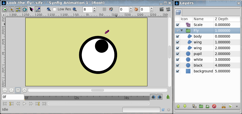
The object of this tutorial is that achieve that one object points to other regardless the movement of both objects. For this tutorial I've selected one moving eye following one moving fly. This is the result you'll obtain:
Create the objects to move
First lets create the fly. In this case I've drawn three Region Layers emulating the two wings and the body. Once created with the Spline Tool, Group them into a Group Layer. It is very important that the fly has to be centered on the Group Layer's Origin. Once grouped the fly layers, the created Group Layer's Origin is at (0,0) so you have to move the fly layers Splines to be around the Group Layer Origin. To do that select all the fly layers, select all the Handles and move them to where the Group Layer Origin is (normally at (0,0)). Once done you can select only the Group Layer and move it around by dragging its Origin's Handle.
Now create the Eye. To create it simply create three Circle Layers: One black in the background (contour of the eyeball), one white in the middle (white eyeball) slightly smaller than the black one, and one smaller black for the pupil. Once created place them in that order and below the fly Group Layer. Rename them properly.
Add a Solid Color Layer for the background and move it down to the bottom.
We are ready to start to make the magic ;)
It should look like this (I have a Zoom Layer added to make a close up screen shot):
First Method, "all by hand"
Export some parameters
- First go to the Group Layer that holds the fly and select the Origin.
- Right click it and select Export and give the name of 'fly'.
- Then go to the 'white' layer and the 'black' layer and select both at the same time. You can do this holding Ctrl meanwhile you click on the layers. Once selected both, the Parameters on the Parameters Panel are slightly different. The common parameters are shown (in this case all them because the layers are the same type) but the parameters that have different values are greyed indicating that.
- Do right click to the Origin and select Link. That would allow to move the origin of both circles as one.
- Now select the 'white' layer.
- Repeat the right click on the Origin and you'll obtain other contextual menu.
- Select Export and name the value node to be 'origin'
- Select Radius parameter and do right click and select Export and name it as 'white radius'.
- Go to the 'pupil' layer and select the Radius parameter of the circle.
- Right click and select Export. Give the name of 'pupil radius'. It will be used later.
Convert pupil's Origin parameter
To make the pupil look at the fly where ever it be, we need to automatically move the pupil based on the fly movement and position. To do that we need to make some geometric work.
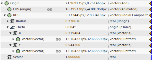
First let's convert the pupil's Origin to Add convert type. To do that select the 'pupil' layer and at the Parameters Panel select the Origin and do right click. At the contextual menu select Convert and in the sub menu select 'Add'. This will add three sub parameters to the Origin.
- Origin
- LHS
- RHS
- Scalar
LHS is for 'Left Hand Side' and RHS is for 'Right Hand Side'. In a addition the order of the elements is not important but for a subtraction it is important.
You can see those sub parameters by clicking on the triangle that appear near the Origin on the left.
Now, we will connect the LHS sub parameter with the origin of the eye, so the position of the pupil is given by the sum of two vectors: the origin of the eye (LHS) and the vector from the eye's origin to the pupil's origin (RHS). To connect the LHS sub parameter first select the Library Panel and expand the Value Nodes list by clicking on the small triangle on the left of the 'Value Node' row. You'll see all the exported value nodes that we did on the previous section of the tutorial. Then select the Origin. This would allow us to use it as the target for the subsequent Connect actions. Go to the Parameters Panel again and do right click on the LHS sub parameter of the Origin. Select Connect from the contextual menu. It will connect the LHS parameter to the exported value node called 'origin' already selected on the Library Panel. It should look like this:
Convert RHS sub parameter
Notice that the sub parameter RHS represents the vector that goes from the eye's origin to the pupils's origin and precisely it is the vector that we want to point to the fly. To make it point to the fly we need to achieve two things:
1) The pupil should not go outside the white eye's radius. 2) The pupil should point to the fly in all moment. It will point to the fly if the direction of the vector from the eye's origin to the pupil's origin has the same direction than the vector that goes from the eyes' origin to the fly's position.
So we need to control the distance and the angle of the vector form the eye's origin to the pupil's origin (that is the RHS). To do this we will convert the RHS in a Radial composite:
Select the RHS sub parameter. Right click on it and select Convert and Radial Composite from the sub menu. It will provide two sub parameters:
- RHS
- Radius
- Theta
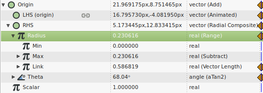
Let's first handle the Radius sub parameter. The first requisite is that the pupil shouldn't go outside the white part radius so we will convert the Radius to be a 'Range' convert type. Use the same procedure: right click the Radius sub-parameter and select Convert and then Range. It will provide the following sub parameters:
- Radius
- Min
- Max
- Link
What does Range do? Range limits the value returned by Link and clamps the value to be between Max and Min. So let's leave the Min sub parameter as its default value (0.0). Now we need to handle the Link and Max values. The Max value should be defined by the pupil and the white circle. I don't like that the pupil bits the black contour so the pupil's origin must be limited by its radius and the white circle radius. If the pupil's radius is smaller, the pupil's origin can be closer to the white circle's radius. To do that we will convert the Max sub parameter to a Subtraction.
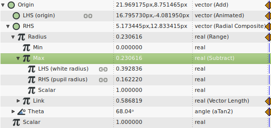
Repeat the same Convert operation over the 'Max' sub parameter and convert it to a Subtract type. It should look like this:
- Max
- LHS
- RHS
- Scalar
This time the RHS and LHS has the following meaning: Max = (LHS-RHS)*Scalar. Leave the Scalar with its default value (0.0) and now let's study the two components of the subtraction. Remember that the Max value represents the maximum distance that the pupil can respect to the eye's origin. So it should be this: Max = white's radius - pupil's radius. Let's do it:
First let's connect the LHS sub parameter to the white's radius. Go to the Library Panel and select 'white radius' previously exported. Then select the LHS sub parameter from the Max sub parameter and right click on it selecting Connect. Repeat same procedure with the 'pupil radius' exported parameter and the RHS sub parameter. It should look like in the previous image.
Now let's handle the Link sub parameter of the Radius sub parameter converted to Range type. The Link represents the radius that we want to limit with the range conversion. It should be the distance between the fly and the eye's origin. If the fly is inside the eye, we don't want to limit the distance, right? that's when range wouldn't modify the Link value. Let's go with it.
- Convert the Link sub parameter to Vector Length. (Do you need that I repeat the procedure??) Then it would provide one sub parameters:
- Link
- Vector
Now convert the Vector into a Subtract type. It will give you again three sub parameters:
- Vector
- LHS
- RHS
- Scalar
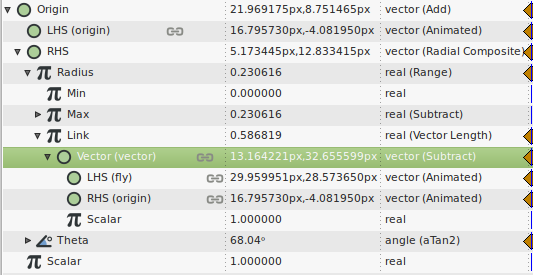
Connect the LHS sub parameter to the 'fly' exported value node and the RHS sub parameter to the 'origin' exported value node. It should look like this:
To be reused later, Export the Vector sub parameter and call it 'vector' as shown in the image.
We have finished with Radius. Now let's go ahead with Theta. Theta is the angle between the horizontal and the vector that goes from the eye's origin to the pupil's origin. We wan it to be the same angle that the fly's origin has with the eye's origin. Angles can be calculated based on vectors coordinates. So we have to first convert the angle Theta into a function that calculates the angle of a vector in function of its coordinates. It is the Convert convert type. Atan2 provides two sub parameters:
- Theta
- X
- Y
Where X and Y are the coordinates of the vector we want to obtain its angle. There are two special convert types that extract the x and y coordinates pf a given vector. They are 'Vector X' and 'Vector Y'. Let's convert the 'X' and 'Y' sub parameters into Vector X and Vector Y respectively. You'll have this:
Now Connect each 'X' and 'Y' sub parameters to the recently exported 'vector' value node, that is the vector from the eye's origin to the fly's origin. We are done!
The conversions are finished!!.
Animate the fly and the eye
Now you can freely animate the eye's origin and the fly's origin and the pupil will always look to the fly. We have achieved the desired effect!
Sample files
Here is the sample file result. Sample file.
Second Method, "vector angle"
How to make this work in Synfig:
- Export the eye Group Origin as "eye.location", and fly group origin as "fly.location"
- Add a Rotate Layer to your eye group, centered on the eye origin.
- Convert it's "Amount" (angle) to Vector Angle and then convert this vector to Subtract.
- Link the subtraction "LHS" to "fly.location" and "RHS" to "eye.location".
Animate the fly and the eye
You can now freely move both the eye and the fly... and keep a close watch on the pest. Math are great, we have achieved the desired effect quicker ! ... isn't it ?
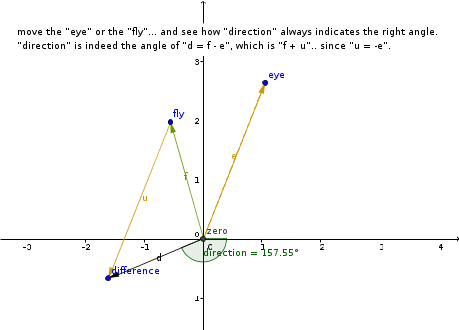
The vector mathematics beyond
| Language: |
English |
