Difference between revisions of "Doc:Creating Shapes/ru"
m |
|||
| Line 42: | Line 42: | ||
Описанных возможностей должно быть достаточно, чтобы вы могли теперь нарисовать какую-нибудь форму сами. | Описанных возможностей должно быть достаточно, чтобы вы могли теперь нарисовать какую-нибудь форму сами. | ||
| + | |||
| + | == Using tablet to draw shapes == | ||
| + | |||
| + | If you have a [http://en.wikipedia.org/wiki/Graphics_tablet graphic tablet] you can use Draw Tool to create BLines. | ||
| + | |||
| + | Synfig Studio supports pressure sensitivity, but you need to configure it first. Go to {{c|File|Input Devices...}} from toolbox menu. In the Input dialog find your tablet's stylus device and set its mode to {{Literal|Screen}}. Click {{Literal|Save}} and then {{Literal|Close}}. | ||
| + | |||
| + | Now grab your stylus, create a new file and click on the Draw Tool button in the toolbox. Set the default line width value to be big enough — say, 15pt — otherwise you will not notice any pressure sensitivity effect. Choose brown as the default fill color. | ||
| + | |||
| + | {{Note|Note|Steps above should be done with the stylus of your tablet, not the mouse. Synfig Studio remembers settings for each input device independently. That's why if you set those options with your mouse device they will not have any effect when you switch to stylus.}} | ||
| + | In the Tool Options Panel, make sure that you have the same options as shown on the screenshot below. | ||
| + | |||
| + | [[Image:DrawToolOptions.png|center|frame]] | ||
| + | |||
| + | Now let's draw some thing like a curvy mountain background. Start drawing a line from the left border to the middle of the canvas. Try to vary your stylus pressure while you are drawing. Stop near the center of the canvas. This is your first line. Notice the new outline layer created in the Layers Panel. | ||
| + | |||
| + | [[Image:Creating-shapes-4-draw.png|center|frame]] | ||
| + | |||
| + | Point your stylus at the last duck of your new BLine and continue drawing to the right border of the canvas. When you finish, look at the Layers Panel again. There's still only one outline layer. Synfig Studio is smart enough to figure out that you don't need a new outline layer and properly extends the last one. You can extend the BLine from both ends, but if you start drawing from any other place of the canvas a new outline layer will be created. Though your first line will remain selected and nothing stops you from extending it later. | ||
| + | |||
| + | Back to our artwork. In the Tool Panel hit the button with the bucket icon to fill the outline we just created. A region layer will appear at the top of the layer we are working with. Select the outline layer and press the {{Literal|Raise Layer}} button in the layers panel to put the outline layer on top of the region. | ||
| + | |||
| + | [[Image:Creating-shapes-5-draw.png|center|frame]] | ||
| + | |||
| + | Extend a line from both sides down to the corners of the canvas to make the fill appear at the bottom. Great. | ||
| + | |||
| + | [[Image:Creating-shapes-6-draw.png|center|frame]] | ||
| + | |||
| + | Go ahead and add a few more lines on top of the filled area to give it a mountain-like look. If brown ducks are in your way, you can hide them by clicking the {{Literal|Toggle vertex ducks}} button at the top of the canvas window (the second one from the left). | ||
| + | |||
| + | [[Image:Creating-shapes-7-draw.png|center|frame]] | ||
| + | |||
| + | {{ | ||
| + | Note|Warning!|Don't use {{Shortcut|Alt|2}} shortcut to turn off visibility of vertex ducks while you using Draw Tool. There's a bug that will cause Synfig Studio to hang.{{DevNotesBegin}} | ||
| + | This bug is fixed in the upcoming release (0.63.00). | ||
| + | {{DevNotesEnd}} | ||
| + | }} | ||
| + | |||
| + | |||
| + | Draw tool is great for drawing complex shapes, but you end up with a bunch of ducks, which are hard to manipulate with the Transform Tool in the way we described above. There are two solutions here. | ||
| + | |||
| + | First, you can increase the {{Literal|Smooth}} value in the Tool Options Dialog while using Draw Tool. That will reduce the count of vertices produced at drawing time, but will make your shape less detailed. | ||
| + | |||
| + | Second, you can use Smooth Move Tool to deform an existing shape. Go for it and click the Smooth Move Tool button in the toolbox. The trick about this tool is that it affects ''selected ducks only''. Press and hold your left mouse button in an empty place of the canvas. Drag to create a selection box. Release the mouse button when you are done. Or just hit {{Shortcut|Ctrl|a}} to select all ducks. Now you can deform the selected segments of BLines. You can change the size of the influence area by tweaking {{Literal|Radius}} in the Tool Options Panel. | ||
| + | |||
| + | What about outline width? There is a Width Tool for that purpose. It is designed for increasing or decreasing the width of a line much like you would with a pencil on paper. Click the Width Tool button in the toolbox, move your stylus over the line you want to change, press and move the cursor back and forth along the line, like you are scratching something. The width of the outline will be increased at the places where you moved the cursor. If you want to decrease the width, just hold "Ctrl" while scratching. Easy! | ||
| + | |||
| + | If you don't want Width Ducks to be displayed, during usage of the Width Tool, just turn them off by pressing the {{Literal|Toggle width ducks}} button at the top of the canvas window. | ||
| + | |||
| + | {{ | ||
| + | Note|Warning!|Don't use {{Shortcut|Alt|5}} shortcut to turn off visibility of width ducks while you using Width Tool. There's a bug that will cause Synfig Studio to hang. | ||
| + | {{DevNotesBegin}} | ||
| + | This bug is fixed in the upcoming release (0.63.00). | ||
| + | {{DevNotesEnd}} | ||
| + | }} | ||
| + | |||
| + | == Other ways to create BLines == | ||
| + | |||
| + | Is that all? Not yet. You can use Circle, Rectangle, Star and Polygon tools to create BLines too. Just check the {{Literal|Create Outline BLine}} and {{Literal|Create Region BLine}} options in the Tool Options Panel when using those tools. | ||
| + | |||
| + | Creating geometric primitive as BLine gives you a better control over it's shape and look. For example, if you want a deformed star, then you can use the Star Tool to create it as outline and region BLines and then use the Transform Tool to deform it. | ||
| + | |||
| + | Now you are ready for the {{L|Doc:Flower Animation|last tutorial}} in this section. Hang on! | ||
Revision as of 15:32, 1 May 2012
|
Warning! This page contains outdated information. The release of Synfig Studio 0.64.0 introduced new terminology and this translated page needs to be updated according to original English text. You can help updating this page - see instructions here. Thank you! |
Рисование произвольных фигур
Основные примитивы, такие как окружности и прямоугольники это, конечно, замечательно, но в жизни всегда хочется чего-то большего. Для рисования произвольных фигур и линий мы используем инструмент BLine.
В программе Synfig с помощью инструмента, носящего имя "BLine" задаются кривые, которые затем превращаются в области или контуры. Аналогом инструмента BLine в других графических программах является инструмент "Path".
Как только вы выберите инструмент BLine, все уТочки на текущем выделенном слое (если таковой имеется) исчезнут, но слой останется выделенным. Это нормально. Всё, что вы создадите с помощью инструмента BLine будет помещено поверх текущего слоя. Просто запомните, что если вы хотите вставить фигуру куда-то в стопке слоёв, вы должны выделить тот слой, поверх которого расположится ваше творение, и только потом включить инструмент BLine — выделение другого слоя после этого автоматически снова включит стандартный инструмент преобразования.
Если вы глянете на панель параметров инструмента, вы увидите там несколько галочек. Убедитесь, что установлены галочки "Fill" ("Заливка") и "Outline" ("Контур"), галочка "Gradient" ("Градиент") снята, а параметр "Feather" ("Растушевка") установлен в ноль. Остальное на данный момент не важно.
|
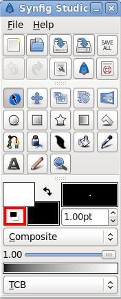
Теперь щёлкните на кнопке "Сбросить цвета до чёрного и белого" слева внизу от ячеек с основным/фоновым цветами на панели инструментов. Это установит основной и фоновый цвета по-умолчанию — чёрный и белый. |
Затем увеличьте толщину линии (справа от ячеек с основным и фоновым цветами) — 10pt должно хватить.
Щелчком левой кнопкой мыши на рабочей области ставятся вершины будущей фигуры. Можно также (и часто нужно!) во время щелчка не отпуская кнопку перемещать мышь — это позволит изменять касательные вершин. Тогда будут получаться не острые углы, а плавные изгибы. Расставляя точку за точкой, вы задаёте кривую Bline, которая и определяет форму вашей фигуры.
Обратите внимание, что в процессе построения кривой ничто не мешает вам изменять положение или наклон касательных уже поставленных ранее точек. Честное пионерское! Если хотите удалить точку, просто щёлкните правой кнопкой на ней и выберите "Delete Vertex" ("Удалить вершину"). Хотите разделить касательную? Нет проблем, щёлкните правой кнопкой мыши на любой из двух уТочек касательной и выберите "Split Tangents" ("Разделить касательную"). Это сделает оба конца касательной независимыми друг от друга. Хотите замкнуть кривую? Щёлкните правой кнопкой мыши на первой вершине и выберите пункт "Loop BLine" ("Замкнуть кривую").
Итак, я могу полагать, что вы разместили свою первую кривую так как захотели. Это прекрасно. Но мы всё ещё находимся в режиме создания кривой - никакие слои ещё не созданы. Завершить создание кривой можно двумя способами:
- просто выбрать другой инструмент
- или нажать кнопку "create" ("создать") в нижней части панели параметров инструмента.
Поэтому сейчас не стесняйтесь и выбирайте инструмент преобразования, так как работать с инструментом Bline мы пока закончили.
Ок, теперь у нас есть симпатичная белая область с толстым чёрным контуром. Обратите внимание, что они представлены двумя слоями – слоем контура и слоем области. Несмотря на то, что это два отдельных слоя, их вершины связаны – так что, если вы будете редактировать один из них, другой будет изменяться соответственно.
Вы хотите управлять вершинами после создания слоя? Нет ничего проще! Просто щёлкните по слою левой кнопкой мыши. Если вы хотите удалить вершину, щёлкните по ней правой кнопкой мыши и выберите "Remove Item (smart)". Хотите добавить ещё одну вершину? Щёлкните правой кнопкой по сегменту, в который вы хотите её добавить, и нажмите "Insert item (smart)".
- Замечание: Единственное заметное отличие между режимом редактирования формы и режимом его создания это то, как разделяются касательные – в режиме создания вы должны щёлкнуть правой кнопкой мыши по самой касательной. При редактировании с помощью инструмента преобразования вам нужно щёлкнуть правой кнопкой по вершине, к которой присоединены касательные. Это можно считать эргономической ошибкой, и мы её когда-нибудь как-нибудь устраним.
Может показаться, что таким образом легко насоздавать кучу неупорядоченных слоёв и потеряться в них. Если вы неправильно используете программу, именно это и произойдёт. Однако на самом деле есть способ избежать этого. Чтобы узнать об этом способе, прочитайте предыдущую главу.
Да, надо ещё упомянуть вот какую вещь. Вы можете изменять толщину контура у каждой вершины. Чтобы сделать это, выберите слой с контуром (обратите внимание, именно с контуром, область к ширине контура не имеет никакого отношения) и отрегулируйте его толщину с помощью уТочек ширины контура. По умолчанию они скрыты. Чтобы сделать их видимыми, нажмите Alt-5. Повторное нажатие Alt-5 спрячет их снова. Какие уТочки отображаются, а какие нет, можно настроить ещё одним способом: нажав кнопку вызова меню и выбрав пункт "View Menu -> Mask Ducks".
Описанных возможностей должно быть достаточно, чтобы вы могли теперь нарисовать какую-нибудь форму сами.
Using tablet to draw shapes
If you have a graphic tablet you can use Draw Tool to create BLines.
Synfig Studio supports pressure sensitivity, but you need to configure it first. Go to "File → Input Devices..." from toolbox menu. In the Input dialog find your tablet's stylus device and set its mode to "Screen". Click "Save" and then "Close".
Now grab your stylus, create a new file and click on the Draw Tool button in the toolbox. Set the default line width value to be big enough — say, 15pt — otherwise you will not notice any pressure sensitivity effect. Choose brown as the default fill color.
|
Note Steps above should be done with the stylus of your tablet, not the mouse. Synfig Studio remembers settings for each input device independently. That's why if you set those options with your mouse device they will not have any effect when you switch to stylus.
|
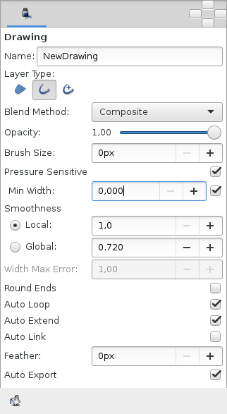
In the Tool Options Panel, make sure that you have the same options as shown on the screenshot below.
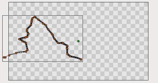
Now let's draw some thing like a curvy mountain background. Start drawing a line from the left border to the middle of the canvas. Try to vary your stylus pressure while you are drawing. Stop near the center of the canvas. This is your first line. Notice the new outline layer created in the Layers Panel.
Point your stylus at the last duck of your new BLine and continue drawing to the right border of the canvas. When you finish, look at the Layers Panel again. There's still only one outline layer. Synfig Studio is smart enough to figure out that you don't need a new outline layer and properly extends the last one. You can extend the BLine from both ends, but if you start drawing from any other place of the canvas a new outline layer will be created. Though your first line will remain selected and nothing stops you from extending it later.
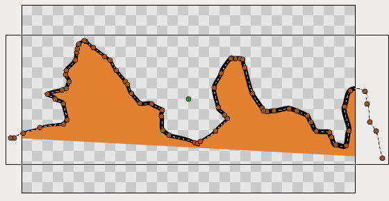
Back to our artwork. In the Tool Panel hit the button with the bucket icon to fill the outline we just created. A region layer will appear at the top of the layer we are working with. Select the outline layer and press the "Raise Layer" button in the layers panel to put the outline layer on top of the region.
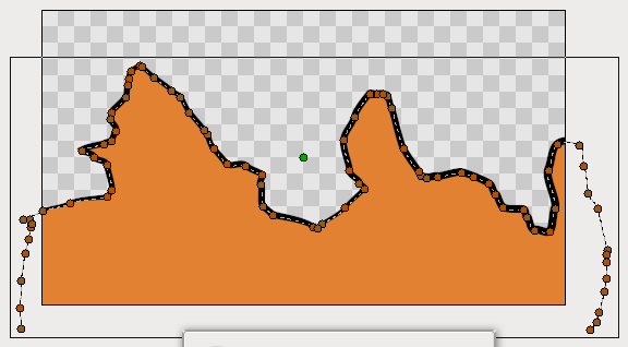
Extend a line from both sides down to the corners of the canvas to make the fill appear at the bottom. Great.
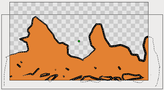
Go ahead and add a few more lines on top of the filled area to give it a mountain-like look. If brown ducks are in your way, you can hide them by clicking the "Toggle vertex ducks" button at the top of the canvas window (the second one from the left).
|
Warning! Don't use Alt2 shortcut to turn off visibility of vertex ducks while you using Draw Tool. There's a bug that will cause Synfig Studio to hang.
Development Notes:
This bug is fixed in the upcoming release (0.63.00). |
Draw tool is great for drawing complex shapes, but you end up with a bunch of ducks, which are hard to manipulate with the Transform Tool in the way we described above. There are two solutions here.
First, you can increase the "Smooth" value in the Tool Options Dialog while using Draw Tool. That will reduce the count of vertices produced at drawing time, but will make your shape less detailed.
Second, you can use Smooth Move Tool to deform an existing shape. Go for it and click the Smooth Move Tool button in the toolbox. The trick about this tool is that it affects selected ducks only. Press and hold your left mouse button in an empty place of the canvas. Drag to create a selection box. Release the mouse button when you are done. Or just hit CtrlA to select all ducks. Now you can deform the selected segments of BLines. You can change the size of the influence area by tweaking "Radius" in the Tool Options Panel.
What about outline width? There is a Width Tool for that purpose. It is designed for increasing or decreasing the width of a line much like you would with a pencil on paper. Click the Width Tool button in the toolbox, move your stylus over the line you want to change, press and move the cursor back and forth along the line, like you are scratching something. The width of the outline will be increased at the places where you moved the cursor. If you want to decrease the width, just hold "Ctrl" while scratching. Easy!
If you don't want Width Ducks to be displayed, during usage of the Width Tool, just turn them off by pressing the "Toggle width ducks" button at the top of the canvas window.
|
Warning! Don't use Alt5 shortcut to turn off visibility of width ducks while you using Width Tool. There's a bug that will cause Synfig Studio to hang.
Development Notes:
This bug is fixed in the upcoming release (0.63.00). |
Other ways to create BLines
Is that all? Not yet. You can use Circle, Rectangle, Star and Polygon tools to create BLines too. Just check the "Create Outline BLine" and "Create Region BLine" options in the Tool Options Panel when using those tools.
Creating geometric primitive as BLine gives you a better control over it's shape and look. For example, if you want a deformed star, then you can use the Star Tool to create it as outline and region BLines and then use the Transform Tool to deform it.
Now you are ready for the last tutorial in this section. Hang on!

